
Abstract
BACKGROUND AND PURPOSE: With modern imaging techniques, visualization of neurovascular stents remains challenging. We present a method for contrast-enhanced C-arm CBCT that provides detailed and simultaneous visualization of neurovascular stents and host arteries.
MATERIALS AND METHODS: CBCT was performed with a rotational angiography system by acquiring 620 projection frames over a 200° arc at 80 kVp and a total of 260 mAs. A superselective intra-arterial contrast injection protocol was optimized in swine experiments and implemented in 57 clinical examinations. High-resolution 3D reconstructions were evaluated by 3 blinded interventional neuroradiologists. Reviewers rated the images by answering questions related to both the quality of the stent and artery visualization and the clinical utility of the images. Raw agreement statistics, ICC, and κ statistics were computed for the questionnaire results.
RESULTS: Of 57 clinical evaluations, 5 were not evaluated due to the use of large balloon-mounted stents (n = 4) and a failed contrast injection (n = 1). In 50 of 52 evaluated examinations, the reviewers agreed that simultaneous stent and vessel visualization was of diagnostic quality. There was strong agreement that stent–vessel wall apposition could be assessed (κ = 0.79). CBCT detected contrast filling defects (κ = 0.85) and vascular calcification (κ = 0.68). Artifacts resulting from the aneurysm coil mass impaired the delineation of adjacent structures (κ = 0.72).
CONCLUSIONS: We have developed a technique that enables simultaneous clinically useful imaging of neurovascular stents and their host arteries that is unobtainable with other current imaging modalities. Further improvements are required to reduce artifacts from large coil masses due to x-ray scattering.
Abbreviations
- ACA
- anterior cerebral artery
- BES
- balloon-expandable stents
- CBCT
- cone-beam CT
- DSA
- digital subtraction angiography
- FDA
- US Food and Drug Administration
- ICA
- internal carotid artery
- ICC
- intraclass correlation coefficient
- MCA
- middle cerebral artery
- MDCT
- multidetector CT
- MIP
- maximum intensity projection
- MRA
- MR angiography
- PICA
- posterior inferior cerebellar artery
- SES
- self-expanding stent
The development of flexible low-profile stents and flow diverters has been a major advancement in the treatment of intracranial atherosclerosis, arterial dissections, and brain aneurysms.1–6 The role of these devices in the treatment and prevention of ischemic and hemorrhagic strokes continues to expand, as has recognition of the importance of assessing the relationship between an implanted device and its host vessel for acute periprocedural success and for long-term biologic response. Such devices are fabricated from metal alloys, typically nickel-titanium (nitinol), platinum, or cobalt-chromium, and have strut or filament diameters of <75 μm—substantially smaller than those of stents designed for coronary and carotid applications. CBCT was first introduced, using image intensifiers, in the 1980s.7 Despite significant imaging improvements with the introduction of newer generation flat panel detectors, visualization of fine stent structures in conjunction with their host vessels remains a significant technical challenge.8–10 We report the development and refinement of a method using C-arm angiographic CT, herein referred to as contrast-enhanced CBCT, and present a review of our early clinical experience with this technique, which enables simultaneous assessment of implants and their host arteries in a variety of neurovascular diseases.
Materials and Methods
Image Acquisition
Images were acquired by using a biplane neuroangiographic unit equipped with 1920 × 2480 cesium iodide−amorphous silicon flat panel detectors covering an area of approximately 30 × 40 cm (Allura Xper FD20/20; Philips Healthcare, Best, the Netherlands). The motorized frontal C-arm, typically used for 3D rotational angiography or soft-tissue-optimized CBCT (reviewed by Orth et al11), was used to acquire 620 projection images over a 200° arc (rotation time, 20.7 seconds) at 80 kVp and a total of 260 mAs. The radiation dose was 49 mGy (weighted CT dose index, measured by using a 16-cm head phantom). The focal spot and source-to-detector distance were 0.4 and 1195 mm, respectively. The objects of interest were positioned in the center of rotation, 810 mm from the source. To maximize spatial resolution, we captured the images in a nonbinned mode, as opposed to the 2 × 2 pixel binning typically used to offer superior contrast resolution for soft-tissue imaging with CBCT. The source projection frames were acquired in a 10162 matrix covering an approximately 155 × 155 mm2 FOV, yielding a pixel size of 0.154 mm. The maximum 3D FOV was 106 mm in each dimension. Postprocessing steps, now commercially available in the manufacturer's software, included gain calibration, scatter correction, white compression inversion, water beam-hardening correction, and Parker weighting.12
In Vivo Experiment
We conducted an in vivo study in the porcine model to optimize the contrast-injection protocol for visualizing the host vascular system without obscuring the fine structures of implants within. All procedures were approved by our Institutional Animal Care and Use Committee. Two male Yorkshire swine, weighing 35 and 60 kg, were anesthetized with an intramuscular injection containing tiletamine/zolazepam (Telazol) (5 mg/kg), xylazine (2.5 mg/kg), glycopyrrolate (0.01 mg/kg), and ketamine (2.5 mg/kg). Anesthesia was maintained with mechanical ventilation of oxygen containing 2% isoflurane. A heparin bolus (100 U/kg) was administered intravenously, and anticoagulation was monitored every hour to maintain the activated clotting time above 250 seconds.
The 3 commercially available FDA-approved intracranial stents (Table 1) were navigated and deployed in the internal maxillary artery in a tandem, nonoverlapping manner. All devices were captured within the FOV. CBCT angiography was performed with a 6F diagnostic catheter positioned in the ipsilateral common carotid artery. Iodinated contrast (iopamidol 51%, Isovue; Bracco Diagnostics, Princeton, New Jersey) was injected at concentrations of 10%, 15%, 20%, 25%, and 30% (by volume in normal saline). In addition, contrast injections for each dilution were performed via a coupled power injector (Mark V ProVis; Medrad, Indianola, Pennsylvania) at rates between 0.5 and 3.5 mL/s for 23 seconds. Acquisition was initiated 2 seconds after the start of contrast injection. The reconstructed datasets were reviewed by the investigators to select an injection protocol that provided the best balance between detailed visualization of stent structures and sufficient opacification of the host vasculature.
Design details of FDA-cleared intracranial stents
By consensus, the optimal injection protocol determined from these swine experiments was 20% of iodinated contrast (iopamidol 51%, Isovue; 250-mg/mL iodine concentration) in normal saline injected into the common carotid artery at 3.0 mL/s for 23 seconds with a 2-second image acquisition delay (Fig 1). These parameters were adopted in the clinical study for imaging devices implanted in the anterior circulation. For imaging of devices in the posterior circulation, vertebral artery injections were performed by using the same contrast concentration at a reduced injection rate of 2.0 mL/s.
Results from an in vivo experiment in the swine model, submental projections from 3D datasets. A, Standard flat-panel contrast-enhanced 2 × 2 binned CBCT (10-mm MIP) following the deployment of 3 stents in the left internal maxillary artery. The distal markers of the Enterprise stent (arrow), Wingspan stent (double arrow), and the Neuroform stent (arrowhead) are marked. B−D, Nonbinned small FOV contrast-enhanced CBCT images for combined stent and vascular visualization are presented at varying contrast concentrations: 10% (B), 20% (C), and 30% (D), all 10-mm MIPs. See “Materials and Methods” for details. Note also the herniation of Wingspan stent struts into the parent artery as it enters a side branch distally (arrow in D).
Clinical Evaluation
This study was approved by our institutional review board. Fifty-seven CBCT examinations of implanted neurovascular stents were performed in 55 consecutive patients undergoing cerebral angiography at our institution between April and October, 2009. One patient received stents in 2 locations during treatments of MCA bifurcation and PICA aneurysms. Another patient received stents in 2 locations during treatments of 2 aneurysms located at the right MCA bifurcation and the M2/M3 division. Each of these was evaluated separately. Five cases in 5 different patients were excluded from the study, 4 due to the use of balloon-mounted cobalt chromium stents that have large struts and, therefore, can be visualized with standard angiography and 1 due to a failed contrast injection. The age of the remaining 50 patients ranged from 18 to 81 years of age (mean, 55.2 years). There were 34 women and 16 men. Most patients (85%, 44/52) were imaged after treatment of intracranial aneurysms by stent-assisted coil embolization. Two patients underwent CBCT to evaluate stents placed before coil embolization. In 6 cases, patients received stents to treat a dissecting vertebral artery aneurysm (n = 1), vertebrobasilar insufficiency resulting from atherosclerotic stenosis (n = 1), acute ischemic stroke (n = 2), and severe MCA stenosis (n = 2). The cases were performed with the patients under either general anesthesia (54%, 28/52) or conscious sedation (46%, 24/52).
The stent-visualization CBCT was reconstructed with a 5123 matrix covering a cubic FOV of 34.44 mm in each dimension (67-μm isotropic voxels). The 3D volumes were assessed through blinded review by 3 experienced interventional neuroradiologists (each with >10 years of experience). The volumetric data were viewed interactively at a prototype reconstruction workstation that provided control over window width and level; slab thickness, position, and rotation; and the choice between MIP and average projection.
Using a standardized questionnaire, the reviewers scored each case for the quality of visualization of the stent and the parent vessel on ordered scales from 1 to 3. In both cases, a score of 1 indicated that visualization was insufficient for evaluation. Stents were graded 2 if sufficient portions of the struts were visible to assess their position and configuration, and 3, if all the struts were visible. The quality of vessel visualization was subjectively assigned a 2 (good) or 3 (excellent). Additionally, the reviewers were asked to provide binary answers (yes/no) to the following questions in applicable cases: 1) Are you able to evaluate stent structures at the level of the coil mass? 2) Is visualization sufficient to assess apposition of the stent to the vessel wall? 3) Can you assess the relationship between the aneurysm, vessels, stent, and coil mass? 4) Is there calcification of the stented segment of the vessel? 5) Are there filling defects within the stented segment? Raw agreement statistics, ICC, and κ statistics were computed for the questionnaire results.
Results
The results of the clinical assessment are summarized in Tables 2 and 3. In 96.1% of cases (50/52), all 3 reviewers rated visualization as sufficient to delineate the configuration and position of each stent (score ≥2). In 100% of these cases, all reviewers agreed that the studies were sufficient to evaluate stent apposition to the vessel wall. All reviewers scored stent-visualization quality as 3 in 61.5% (32/52) of cases. Statistical agreement on the scoring of stent visualization in all cases was strong (ICC=0.67). The reviewers agreed that vessel visualization was sufficient for evaluation (score, ≥2) in all except 1 case (98.1%). This was 1 of the cases in which stent visualization was not thought by all reviewers to be sufficient. In 73.1% (38/52) of cases, all reviewers scored vessel visualization as 3. Statistical agreement on the scoring of stent visualization was only fair (ICC=0.27), due to variability in the assignment of scores 2 and 3. The reviewers agreed that stents could be seen at the level of embolization coil masses in 25% (11/44) of cases in which coils were present (κ=0.69). In all of these cases, the raters agreed that the relationship between the aneurysm, vessels, stent, and coil mass could be assessed. Calcification was detected along the stented segment by all reviewers in 3.85% (2/52) of cases, with unanimous agreement as to the presence or absence of calcification in 94.2% (49/52) of cases (κ=0.68). Filling defects were seen by all reviewers in 11.5% (6/52) of cases. Agreement as to the presence or absence of filling defects was unanimous in 94.2% (49/52) of cases (κ=0.85).
Results of ordered-scale questions
Results from binary questions
In 15 of 52 cases, CBCT identified findings that could not be clearly delineated on conventional DSA or 64-detector MDCT, including filling defects (n = 6), calcification along the stented segment (n = 2), and stent malapposition (n = 7). In 1 case, CBCT provided important real-time data regarding the aneurysm-vessel-stent–coil mass relationship. The following cases illustrate these observations.
Illustrative Cases
Case 1.
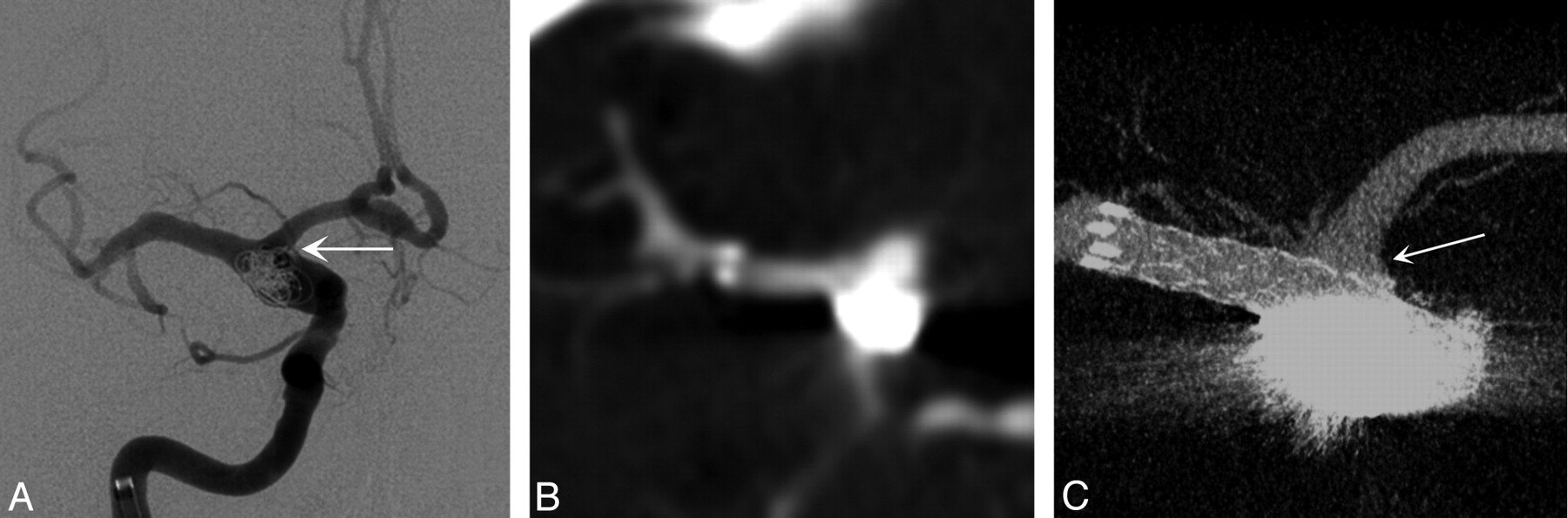
A 61-year-old woman presented with a complex fusiform aneurysm of the ICA bifurcation. A stent was placed from the distal ICA into the proximal MCA. Neither conventional DSA (Fig 2A) nor MDCT angiography done retrospectively, after the procedure, (Fig 2B) could delineate the relationship between the coils placed in the aneurysm, the A1 segment of the ACA, and the stent. Intraoperative CBCT clearly delineated excellent stent apposition, that the ostium of the patent A1 segment was protected by the stent, and that there was no coil mass herniation into the A1 (Fig 2C). If coil mass herniation or stent malapposition to the A1 ostium had been detected, a second stent could have been deployed via the anterior communicating artery to protect the A1.

A, Intraprocedural frontal DSA image acquired during stent-assisted coiling of a right ICA dissecting fusiform aneurysm in a 61-year-old woman. Multiple DSA projections (not shown) were unable to define the coil mass position within the aneurysm and exclude material herniation into the A1 (arrow). B, Postprocedural conventional 64-detector MDCT source image with contrast offers no details of the devices or the adjacent vascular structures (0.95-mm source image). C, Contrast-enhanced CBCT (2.5-mm MIP) clearly shows the stent protecting the right A1 (arrow) and the coil mass secured within the aneurysm boundary.
Case 2.
A 43-year-old woman presented with an acute ischemic stroke. After multiple unsuccessful attempts at revascularization by using intra-arterial tissue plasminogen activator and conventional mechanical thrombectomy devices, a Wingspan stent was placed through the area of residual stenosis. Filling defects remained in the stented segment (Fig 3A), but the poor visibility of the stent limited our ability to discriminate between an underlying atherosclerotic lesion causing stent narrowing and an acute thrombus within a fully expanded stent. CBCT clearly depicted complete expansion of the Wingspan stent (Boston Scientific Neurovascular, Fremont, California) and a large eccentric filling defect consistent with thrombus (Figs 3B, -C). On the basis of the confirmation that this defect was within the stent rather than compressing it from the outside, we selected thrombolytic therapy over poststent angioplasty.

A, Intraprocedural left-anterior-oblique DSA image acquired after primary stent placement in an acute ischemic stroke associated with an atherosclerotic lesion in a 43-year-old woman shows a filling defect of the left MCA (arrowhead). B and C, Contrast-enhanced CBCT in the same projection (5.0-mm MIP, B) and a cross-sectional projection (1.0-mm MIP, C) demonstrate that the filling defect is most likely a clot (asterisk) on the stent surface (arrows indicate struts) rather than plaque material deforming the stent extrinsically.
Case 3.
This case was a follow-up of a 62-year-old woman who presented 16 months prior with >80% stenosis of the M1 segment of the left MCA. The lesion was treated by angioplasty and placement of a Wingspan stent. On follow-up, the stent was seen to be patent on DSA (Fig 4A). CBCT showed complete expansion of the stent and a thin crescentic filling defect along the inner surface of the stent (Figs 4B, -C). Given the location, morphology, and time course, this finding was consistent with neointimal hyperplasia.

A, Left-anterior-oblique DSA image at 16 months after intracranial stent placement for an atherosclerotic stenosis of the left MCA in a 62-year-old woman. B and C, Contrast-enhanced CBCT scans, left-anterior oblique projection (5.0-mm MIP, B) and cross-sectional projection (1.0-mm MIP, C), show a focal and asymmetric neointimal hyperplasia (arrows) and eccentric stent narrowing related to the presence of underlying atherosclerotic plaque, not appreciated on DSA.
Case 4.
A patient was imaged during 6-month follow-up evaluation of an unruptured right superior hypophyseal artery aneurysm. The sharp curvature of the carotid artery in this location correlates with the anatomic configuration previously shown in vitro to cause kinking of the closed-cell Enterprise stent (Codman Neurovascular, Raynham, Massachusetts).13 CBCT allowed us to demonstrate this abnormality in vivo (Fig 5).
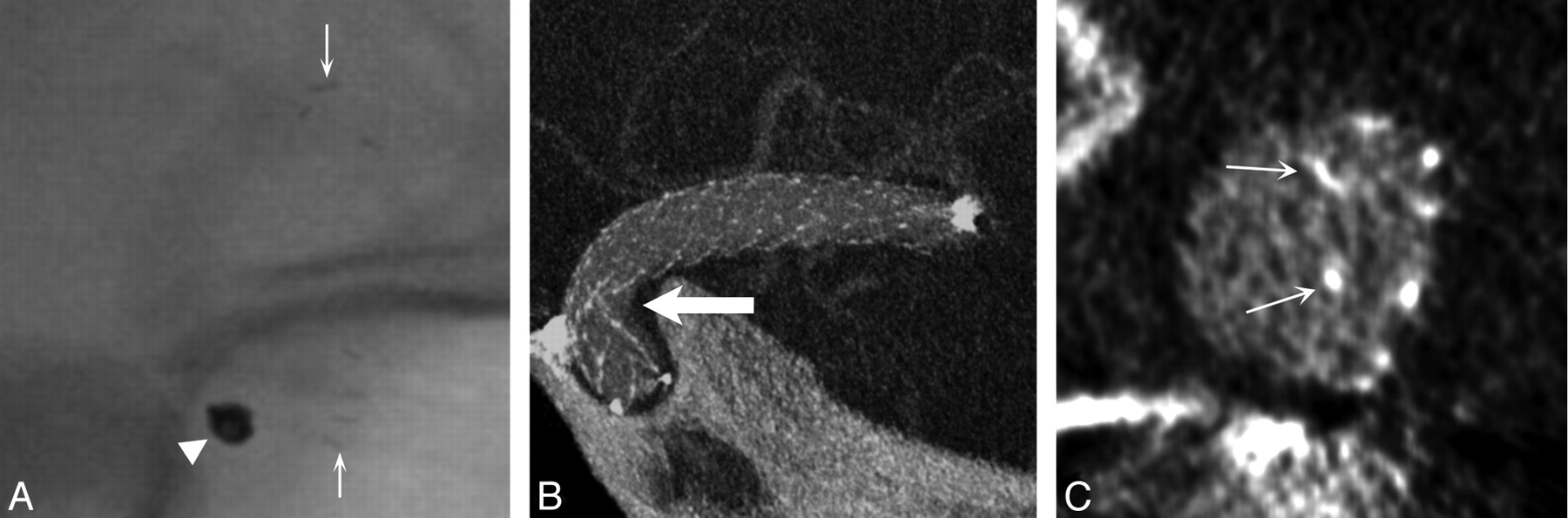
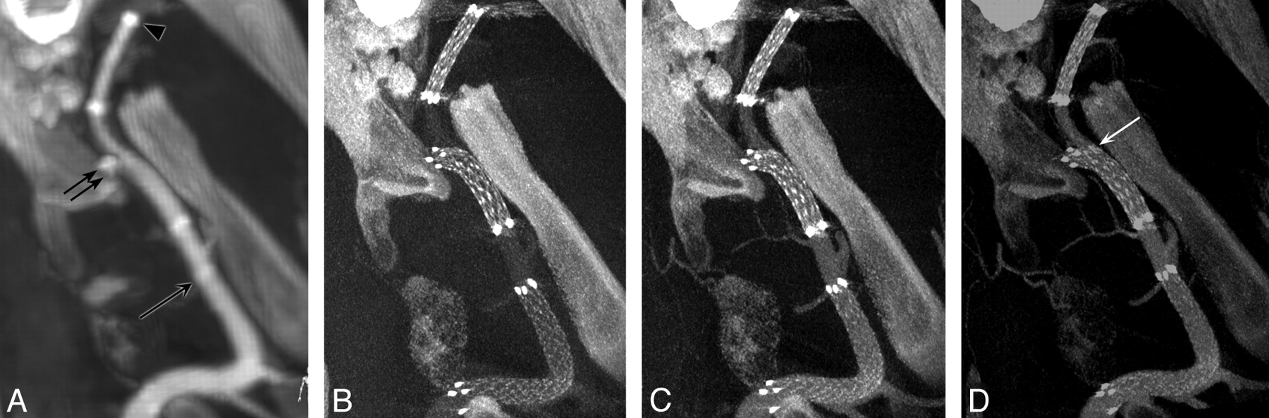
A, Follow-up unsubtracted x-ray image acquired at 6 months after stent-assisted coiling of a right superior hypophyseal artery aneurysm does not show any stent struts. Arrows show proximal and distal stent markers, and the arrowhead shows the coil mass. B, Contrast-enhanced CBCT in an oblique projection (2.5-mm MIP) indicates that the stent is kinked at the inner radius of the carotid siphon (arrow). C, The cross-sectional view (1.0-mm average intensity projection) of the stent device shows that the struts are malposed to the walls of the parent artery (arrows).
Case 5.
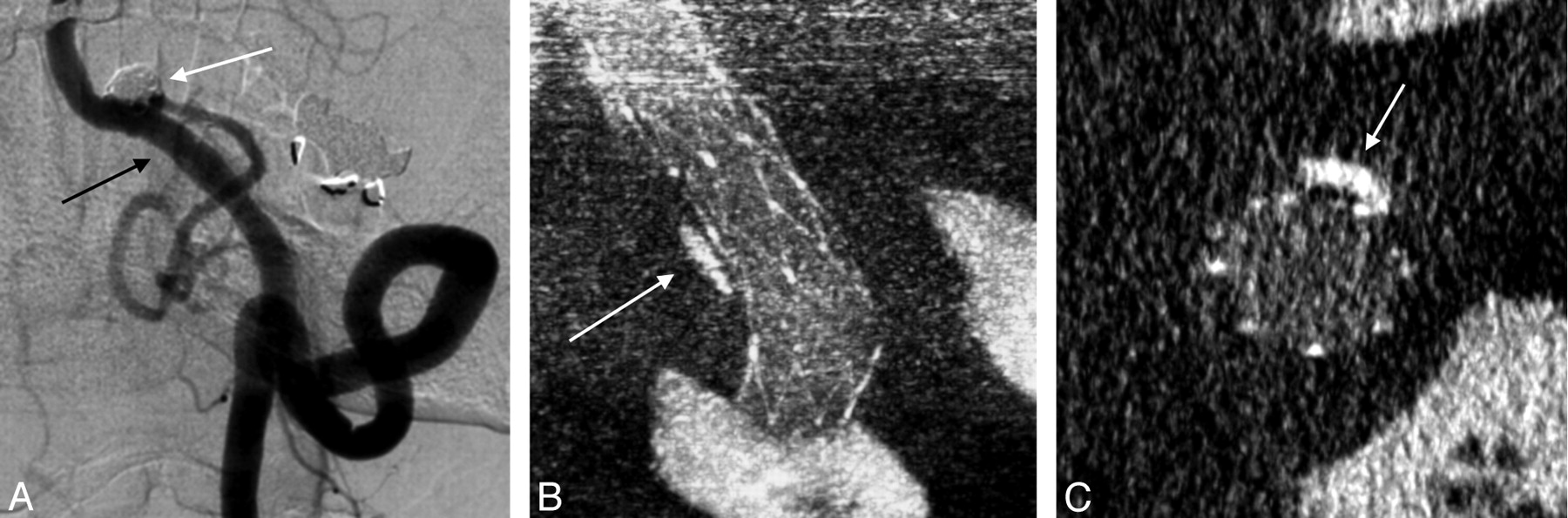
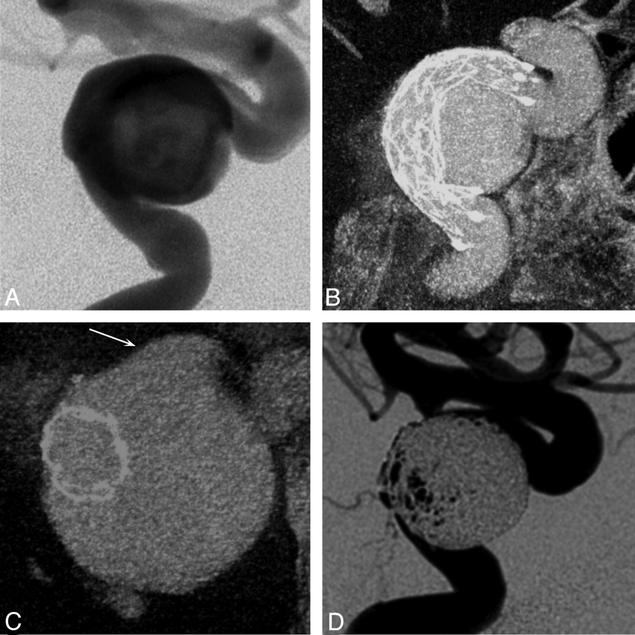
A patient with thromboembolic stroke associated with a large ipsilateral aneurysm of the cavernous carotid artery was treated electively with stent-assisted coil embolization. CBCT provided information on the angioarchitecture of the aneurysm–parent vessel complex (Fig 6). Moreover, CBCT performed intraoperatively defined simultaneously the stent-constructed boundaries and the aneurysm pouch. This definition facilitated the selection of working projections critical for a coil embolization.

A 66-year-old woman presented with acute thromboembolic stroke related to a large left cavernous carotid aneurysm. A, DSA in a lateral projection, after stent implantation, does not clearly depict the stent or its relationship to the host artery and aneurysm. B and C, Contrast-enhanced CBCT in projections longitudinal (5.0-mm MIP, B) and cross-sectional (2.5-mm MIP, C) to the stent shows the complex nature of the fusiform aneurysm, its intradural extension (arrow), and the apposition of the stent within the host artery. D, The operator can clearly evaluate the newly established vessel boundary and the remaining aneurysmal component, which was subsequently embolized.
Case 6.
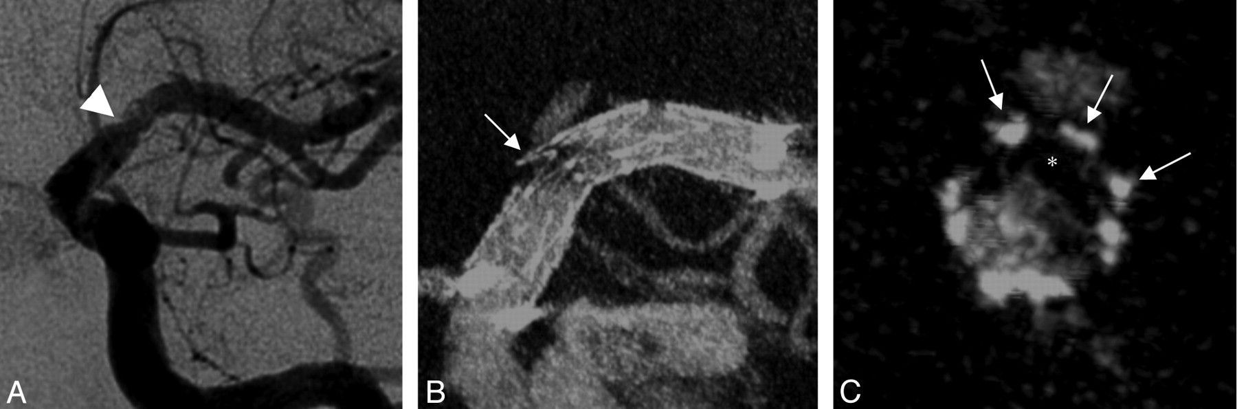
A 75-year-old man was treated for a left PICA aneurysm with stent-assisted coiling. DSA performed at 2-year follow-up showed a focus of luminal irregularity along the distal aspect of the stent but could not confirm whether this was within or outside the stent. CBCT demonstrated a calcified atherosclerotic plaque in this diseased arterial segment and helped to differentiate atheroma outside the stent from neointimal hyperplasia within it (Fig 7).
A, Two-year follow-up DSA of a left posterior inferior cerebellar artery aneurysm (white arrow), which had been coiled with the support of 2 telescoping stents. Note the vessel wall irregularity within the stented area opposite the coiled aneurysm (black arrow). B and C, On contrast-enhanced CBCT in longitudinal (2.5-mm MIP, B) and cross-sectional views (0.5-mm MIP, C), this irregularity corresponds to underlying calcified atherosclerotic disease rather than neointimal hyperplasia (arrows).
Discussion
Technologic advancement in the endovascular treatment of ischemic and hemorrhagic neurovascular diseases poses new challenges for the imaging of implants. Stent technology, in particular, is finding broader applications for preventative and therapeutic revascularization in ischemic stroke and for vascular reconstruction during coil embolization of brain aneurysms (reviewed in Gounis et al14 and Wakhloo et al15). However, visualization of neurovascular stents by using current imaging modalities such as MDCT angiography and MRA is limited by artifacts and a lack of sufficient spatial resolution.8,9 Furthermore, the neurovascular stents currently in use are not sufficiently radiopaque to be evaluated well by using conventional angiography. Thus, by using standard techniques, our ability to evaluate the configuration of these devices, their relationships to the host vasculature, and potential complications has been limited.
We present here the development and clinical application of a method for contrast-enhanced CBCT that provides visualization of a variety of neurovascular stents in conjunction with their host arteries.
After experimental refinement of the acquisition parameters and contrast-injection protocol, clinical evaluation demonstrates successful imaging of the implant-host artery relationship with sufficient detail to directly assess the position and configuration of stents, their apposition to their host vessel, filling defects within them, and important relationships between the stents and other structures. Unlike MDCT or MRA, CBCT can be performed intraoperatively, linking imaging to intervention and providing critical real-time information for therapy.
BES, the prevailing technology for coronary applications, remain useful in the treatment of vertebrobasilar atherosclerotic stenosis and, less commonly, for intracranial atherosclerosis. These devices have stent-strut thicknesses of approximately 0.1 mm and are usually fabricated from 316L stainless steel or cobalt-chromium alloys. Because of the thickness of their struts and the high radiopacity of the alloys from which they are fabricated, BES are relatively easily seen on MDCT angiography and DSA, as well as with CBCT.
Newer SESs are designed specifically for intracranial applications. SESs, now commonly used in the clinical setting, are made from super-elastic nitinol, enabling low-profile devices with a strut thickness of approximately 0.06 mm that are deliverable through microcatheters. The visibility of these devices under fluoroscopy is limited by the decrease in strut thickness and poor attenuation offered by nitinol. Some measures, such as the inclusion of radiopaque markers, have been used to address this limitation. However, these markers provide little information regarding the configuration of a stent. Thus, the visibility of SESs remains challenging. We have targeted the imaging of SESs because of their limited visibility and because these are the most commonly used stents today in the intracranial circulation.
The Neuroform stent (Boston Scientific) is the first SES approved by the FDA for intracranial use. This stent has an open-cell design that provides excellent flexibility and conformity to the host vessel wall. However, when placed around vascular bends in the intracranial circulation, the stent struts have a propensity to herniate into the origin of side branches. Most commonly, herniation is observed within the neck of an aneurysm.16 On the other hand, closed-cell stents, such as the Enterprise vascular reconstruction device, may ovalize or kink (case 4) when implanted around tight bends.13 CBCT allows the in vivo detection of this malapposition. The advantage of such information provided by intraoperative CBCT, combined with a resheathable stent (semi-jailing technique previously described in Hong et al17), permits corrective repositioning in the event of ovalization.
Although the clinical significance of neurovascular stent malapposition is not well understood, it raises important concerns. Studies on coronary stent placement have shown a strong association between incomplete neointimal coverage of stent struts and the development of stent thrombosis.18 Histologic data demonstrate that the neointima grows over stent struts in response to endothelial injury sustained during stent expansion.18,19 Incompletely expanded stents may prevent proper neointimal coverage, exposing the treated segment to thrombosis and thromboembolism. Stent thrombosis and thromboembolism are the most common adverse sequelae of stent use in the intracranial circulation. Thus, an understanding of the factors that contribute to stent malapposition is of significant impact.6,20,21 In addition, malapposed stents can mechanically impair re-entry to stented vessels, for subsequent retreatment of the aneurysm or distal vascular access.
In the setting of an acute ischemic stroke, the distinction between a flow-limiting thrombus and underlying atheroma, in case of a successful revascularization, can influence the further treatment (ie, continued thrombolysis or thrombectomy versus angioplasty). Moreover, the ability to detect acute thrombosis and, over the longer term, neointimal hyperplasia may have important implications for device development to prevent adverse biologic responses.
Perhaps the largest weakness of the study was the low κ statistic for agreement on the quality of vessel visualization because the distinction between scores 2 and 3 was subjective. Although poor statistical agreement was realized with regard to vascular image quality, the raw agreement was nearly complete (51/52 cases) in supporting the hypothesis that our method yields sufficient visualization for assessment (score ≥2). Improved agreement on the scores related to stent visualization was realized due to the well-structured scale.
The chief technical limitation to CBCT in the setting of stent-assisted coil embolization is that streak artifacts caused by a radiodense coil mass obscure portions of the stent, particularly limiting evaluation of the relationship between the aneurysm, arteries, stent, and coil mass. This limitation has been encountered by other investigators and is related to the size of the coil mass.22 Although our current technique offers significant advantages to the visualization of the stent-artery relationship, it remains invasive and requires local intra-arterial delivery of contrast. As previously described,23 we are currently evaluating CBCT acquisitions with intravenously administered contrast, which may offer a noninvasive alternative for the follow-up of patients with neurovascular stents. The reliability of CBCT imaging was not significantly impaired by the large proportion of patients imaged without general anesthesia in our study; this finding further substantiates the potential of a less invasive approach. Finally, a new class of devices, flow diverters, is being introduced for brain aneurysm treatment. Flow diverters have strut dimensions on the order of ≤0.03 mm, and it remains to be determined if this imaging protocol will offer sufficient spatial resolution for detailed visualization of these devices.4,24
CBCT combines the contrast resolution necessary for distinguishing metallic stents from contrast-opacified vessels with the substantially increased spatial resolution of the flat panel detector arrays used for angiography. Prior investigators have capitalized on this increase in spatial resolution to show that CBCT is capable of depicting neurovascular SESs with good detail in vitro and in vivo.13,16,22,25,26 Other work has shown that CBCT has the contrast resolution required to provide simultaneous visualization of BES and a contrast-opacified host vessel, though at relatively lower detail.23 The refined technique we present here demonstrates that contrast-enhanced CBCT can reliably provide detailed images of the newer generation of neurovascular stents, particularly low-visibility SESs, in conjunction with their host arteries. In ongoing research, we are working to address the technical limitations outlined above and to broaden our understanding of the implications that CBCT might have for the treatment of other neurovascular diseases. We see particular promise for this technology in the treatment of arteriovenous malformations, dural arteriovenous fistulas, and tumors, in which very high spatial resolution may reveal important vascular anatomy and lead to improved therapeutic approaches.
Conclusions
Using a protocol developed in a preclinical model, we assessed the clinical application of CBCT in neurovascular stent procedures. The clinical evaluation demonstrated that the technology enables simultaneous imaging of neurovascular stents and their host arteries that is not obtainable with other imaging modalities. These preliminary data suggest a role for intraoperative CBCT to provide important information during neurovascular stent-placement procedures and guide future device development.
Footnotes
-
This work was funded in part by research grants from Philips Healthcare and the National Institutes of Health (R21-EB007767).
-
The contents are solely the responsibility of the authors and do not necessarily represent the official views of Philips Healthcare or the National Institutes of Health.
Indicates open access to non-subscribers at www.ajnr.org
References
- Received March 15, 2010.
- Accepted after revision May 30, 2010.
- Copyright © American Society of Neuroradiology
In this issue


Jump to section
Related Articles
Cited By...
- Principles, techniques and applications of high resolution cone beam CT angiography in the neuroangio suite
- Principles, techniques and applications of high resolution cone beam CT angiography in the neuroangio suite
- Combination of high-resolution cone beam computed tomography and metal artefact reduction software: a new image fusion technique for evaluating intracranial stent apposition after aneurysm treatment
- Fast acquisition cone-beam computed tomography: initial experience with a 10 s protocol
- Radiation Dosimetry of 3D Rotational Neuroangiography and 2D-DSA in Children
- Quantitative Analysis of Conebeam CT for Delineating Stents in Stent-Assisted Coil Embolization
- Wall Apposition Is a Key Factor for Aneurysm Occlusion after Flow Diversion: A Histologic Evaluation in 41 Rabbits
- Grading of Regional Apposition after Flow-Diverter Treatment (GRAFT): a comparative evaluation of VasoCT and intravascular OCT
- Intravenous C-Arm Conebeam CT Angiography following Long-Term Flow-Diverter Implantation: Technologic Evaluation and Preliminary Results
- High-Resolution C-Arm CT and Metal Artifact Reduction Software: A Novel Imaging Modality for Analyzing Aneurysms Treated with Stent-Assisted Coil Embolization
- Adjunctive value of intra-arterial cone beam CT angiography relative to DSA in the evaluation of cranial and spinal arteriovenous fistulas
- Quantitative analysis of high-resolution, contrast-enhanced, cone-beam CT for the detection of intracranial in-stent hyperplasia
- Role of C-Arm VasoCT in the Use of Endovascular WEB Flow Disruption in Intracranial Aneurysm Treatment
- Hemodynamics of 8 Different Configurations of Stenting for Bifurcation Aneurysms
- Surveillance imaging after intracranial stent implantation: non-invasive imaging compared with digital subtraction angiography
- Successful detection of embologenic ulceration in a symptomatic non-hemodynamic intracranial stenosis using C-arm cone beam CT
- Frameless multimodal image guidance of localized convection-enhanced delivery of therapeutics in the brain
- Double-barrel entanglement of intracranial Enterprise stents resulting from undetected incomplete stent apposition
- The Effect of Intracranial Stent Implantation on the Curvature of the Cerebrovasculature
- Advances in Stroke: Advances in Interventional Neuroradiology