Advertisement

Main menu

  • Home
  • Content
    • Current Issue
    • Publication Preview--Ahead of Print
    • Past Issue Archive
    • Case of the Week Archive
    • Classic Case Archive
    • Case of the Month Archive
  • For Authors
  • About Us
    • About AJNR
    • Editors
    • American Society of Neuroradiology
  • Submit a Manuscript
  • Podcasts
    • Subscribe on iTunes
    • Subscribe on Stitcher
  • More
    • Subscribers
    • Permissions
    • Advertisers
    • Alerts
    • Feedback
  • Other Publications
    • ajnr

User menu

  • Subscribe
  • Alerts
  • Log in

Search

  • Advanced search
American Journal of Neuroradiology

American Journal of Neuroradiology

  • Subscribe
  • Alerts
  • Log in

Advanced Search

  • Home
  • Content
    • Current Issue
    • Publication Preview--Ahead of Print
    • Past Issue Archive
    • Case of the Week Archive
    • Classic Case Archive
    • Case of the Month Archive
  • For Authors
  • About Us
    • About AJNR
    • Editors
    • American Society of Neuroradiology
  • Submit a Manuscript
  • Podcasts
    • Subscribe on iTunes
    • Subscribe on Stitcher
  • More
    • Subscribers
    • Permissions
    • Advertisers
    • Alerts
    • Feedback
  • Follow AJNR on Twitter
  • Visit AJNR on Facebook
  • Follow AJNR on Instagram
  • Join AJNR on LinkedIn
  • RSS Feeds
Research ArticleHead & Neck

High-Resolution Secondary Reconstructions with the Use of Flat Panel CT in the Clinical Assessment of Patients with Cochlear Implants

M.S. Pearl, A. Roy and C.J. Limb
American Journal of Neuroradiology June 2014, 35 (6) 1202-1208; DOI: https://doi.org/10.3174/ajnr.A3814
M.S. Pearl
aFrom the Division of Interventional Neuroradiology (M.S.P.)
cInterventional Neuroradiology (M.S.P.), Children's National Medical Center, Washington, DC
  • Find this author on Google Scholar
  • Find this author on PubMed
  • Search for this author on this site
A. Roy
bDepartment of Otolaryngology–Head and Neck Surgery (R.R., C.J.L.), Johns Hopkins University School of Medicine, Baltimore, Maryland
  • Find this author on Google Scholar
  • Find this author on PubMed
  • Search for this author on this site
C.J. Limb
bDepartment of Otolaryngology–Head and Neck Surgery (R.R., C.J.L.), Johns Hopkins University School of Medicine, Baltimore, Maryland
dPeabody Conservatory of Music (C.J.L.), Baltimore, Maryland.
  • Find this author on Google Scholar
  • Find this author on PubMed
  • Search for this author on this site
  • Article
  • Figures & Data
  • Info & Metrics
  • References
  • PDF
Loading

Article Figures & Data

Figures

  • Tables
  • Fig 1.
    • Download figure
    • Open in new tab
    • Download powerpoint
    Fig 1.

    Flat panel CT of a right-sided cochlear implant. A, Collimated fluoroscopic acquisition for a 20-second FPCT of a right-sided CI. The skull above and below is excluded from the initial acquisition. B, Example of a coronal oblique image acquired after the default reconstruction. C, Secondary reconstruction by use of a manually generated voxel of interest is created to include only the electrode array. D, Higher-resolution coronal oblique image is generated after the secondary reconstruction.

  • Fig 2.
    • Download figure
    • Open in new tab
    • Download powerpoint
    Fig 2.

    Multiplanar reconstruction images of a right-sided cochlear implant. Multiplanar reconstruction axes are aligned parallel to the basal turn on the axial (A) and sagittal (B) planes to generate a coronal oblique (C) image of the CI. This image is rotated slightly to visualize the vestibule and superior semicircular canal. Arrow in (C) denotes the insertion point.
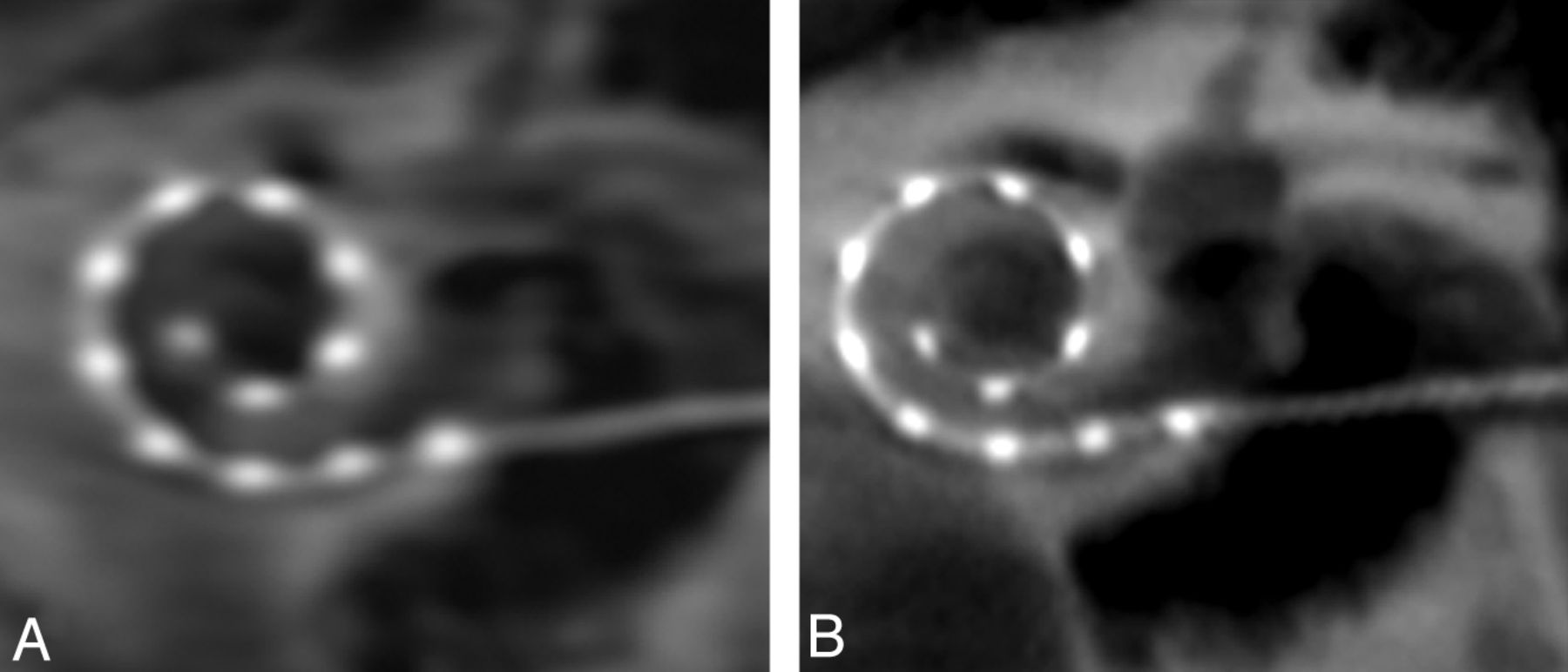
  • Fig 3.
    • Download figure
    • Open in new tab
    • Download powerpoint
    Fig 3.

    Secondary reconstructions comparing edge enhancement (A) and Hounsfield unit (HU) (B) kernel type show more distinct individual electrode contacts and osseous structures on the image generated by HU kernel type.

  • Fig 4.
    • Download figure
    • Open in new tab
    • Download powerpoint
    Fig 4.

    Coronal oblique secondary reconstructions of the same patient with cochlear implants. These images illustrate the variable image quality obtained with identical 3-mm section thickness, window width (3681), contrast (1246), and kernel type (HU). Note the blurring and poor visualization of the electrode contacts with the very smooth (A) setting. A sharp (D) parameter produces optimal images with well-defined osseous structures and individual electrode contacts. (A) Very smooth, (B) normal, (C) auto, (D) sharp.

  • Fig 5.
    • Download figure
    • Open in new tab
    • Download powerpoint
    Fig 5.

    High-resolution secondary reconstructions of all 14 patients and 18 cochlear implants (CIs). A–I, Nine right-sided CIs, including 1 patient (I) with an implanted medium array, are shown in the coronal oblique plane. J–R, Nine left-sided CIs are depicted, all of which are the standard length array. Images are arranged in order of descending angular insertion depth. All 216 individual electrode contacts are clearly visualized in all patients.
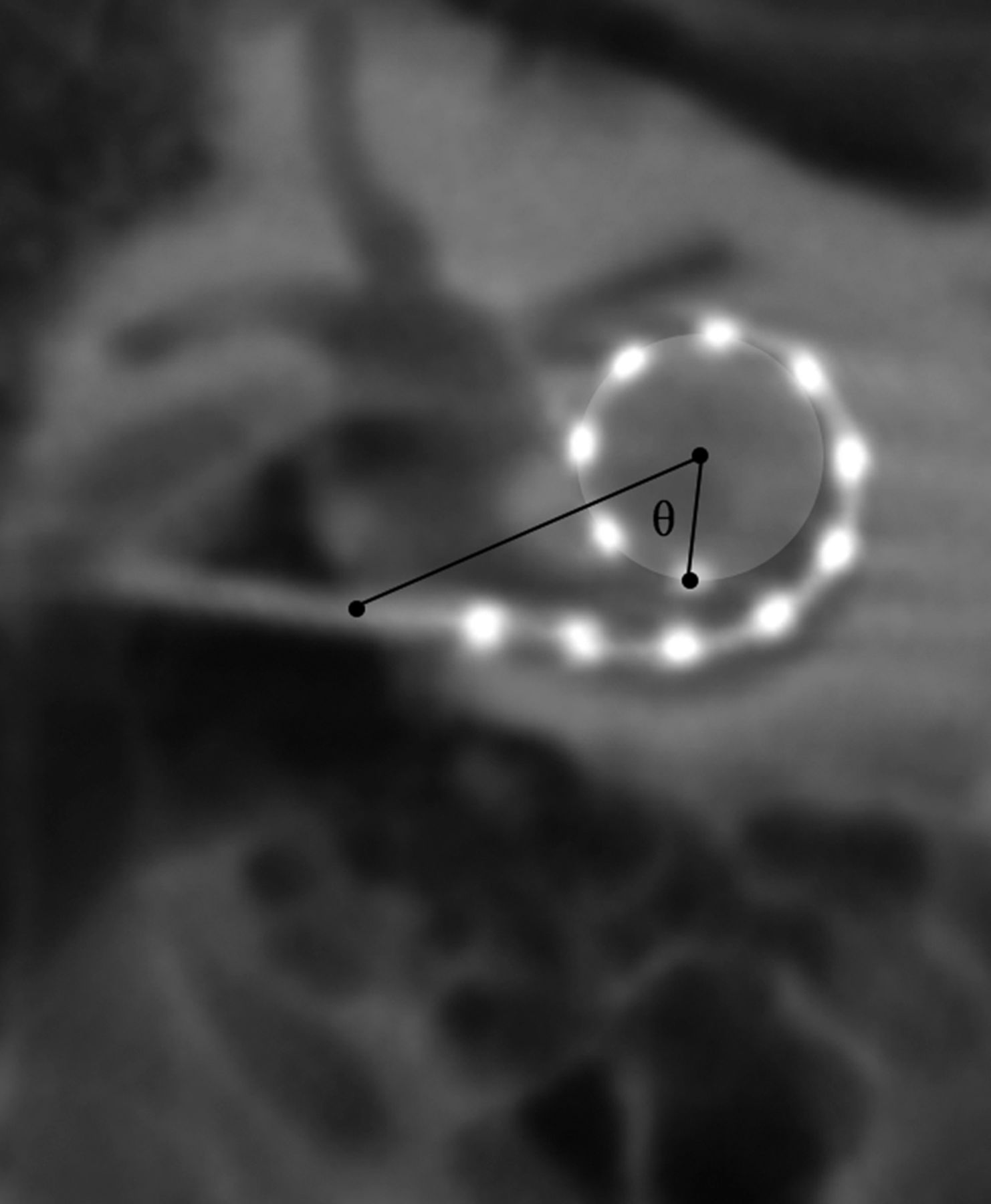
  • Fig 6.
    • Download figure
    • Open in new tab
    • Download powerpoint
    Fig 6.

    Method for calculating the angular insertion depth of the most apical electrode. The insertion point, as determined by the axial and sagittal images (not shown) is designated in the coronal oblique image. A circle whose outer circumference represents the trajectory of the 3 most apical electrodes is drawn. A reference line is drawn between the insertion point and the center of this circle. The most apical electrode is then identified and the angle θ is calculated between the electrode and the reference line. In this example, angular insertion depth is calculated by 360 ± θ.
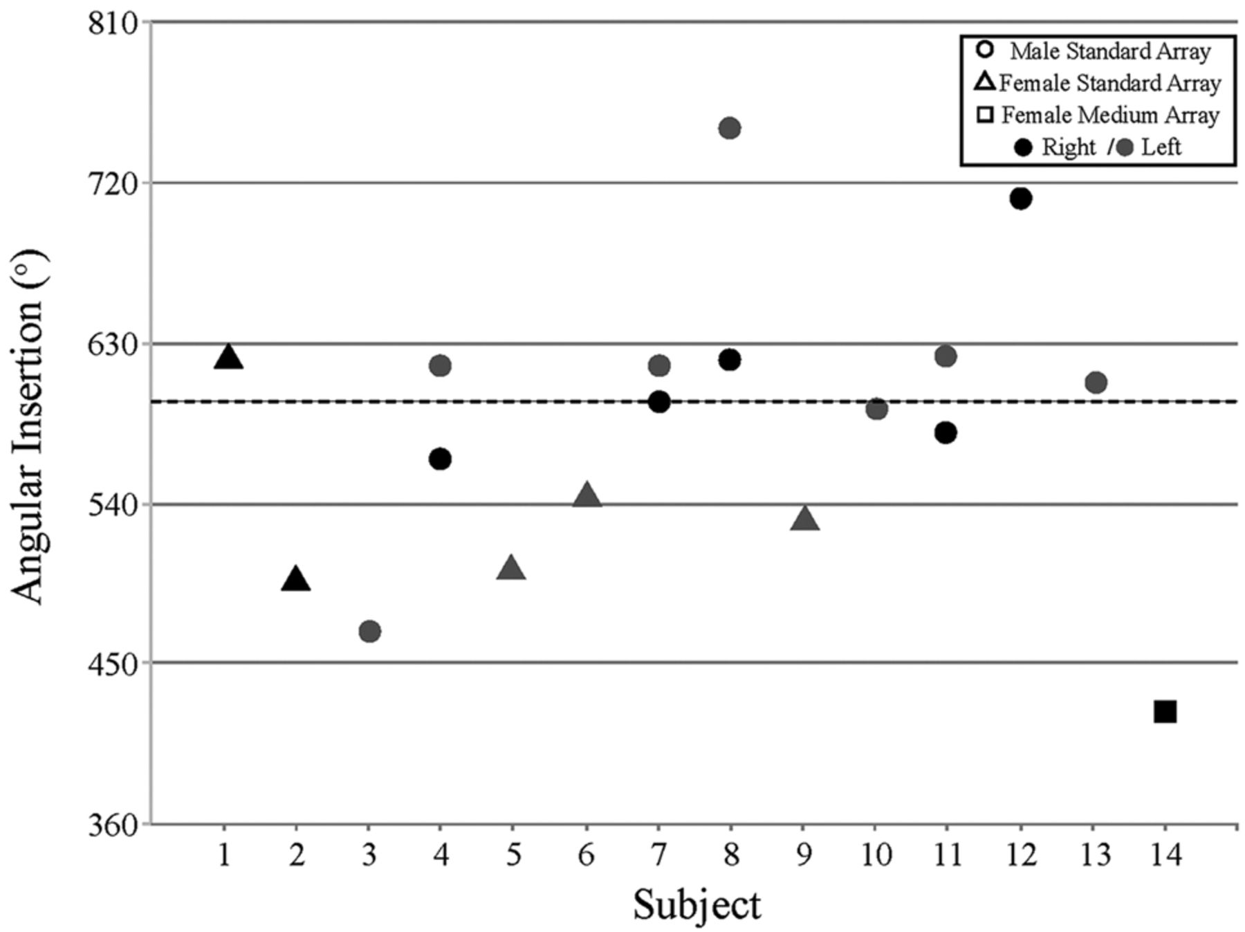
  • Fig 7.
    • Download figure
    • Open in new tab
    • Download powerpoint
    Fig 7.

    Measured angular insertion depth of the most apical electrodes. Circles and triangles depict angular insertion depth for male and female patients with Med-El 31.5-mm standard array, respectively. Square refers to the single Med-El 24-mm medium array patient. Black filled shapes depict a right implanted ear; gray filled shapes depict a left implanted ear.

Tables

  • Figures
    • View popup
    Table 1:

    Demographic information for patients with cochlear implants

    SubjectSexAge, yEtiologyImplant DeviceImplant SideFig 5RW Insertion
    1F59MeniereMed-El Sonata, Standard ArrayRightB
    2F48AutoimmuneMed-El Sonata, Standard ArrayRightHRW
    3M62MeniereMed-El Sonata, Standard ArrayLeftRRW
    4aM51IdiopathicMed-El Concert, Standard ArrayRightFRW
    Med-El Concert, Standard ArrayLeftL
    5F54HereditaryMed-El Concert, Standard ArrayLeftQ
    6F21IdiopathicMed-El Sonata, Standard ArrayLeftP
    7aM59MeniereMed-El Concert, Standard ArrayRightD
    Med-El Sonata, Standard ArrayLeftM
    8aM62IdiopathicMed-El Sonata, Standard ArrayRightCRW
    Med-El Sonata, Standard ArrayLeftJ
    9F51IdiopathicMed-El Concert, Standard ArrayRightGRW
    10M61MeniereMed-El Concert, Standard ArrayLeftO
    11aM57IdiopathicMed-El Sonata, Standard ArrayRightE
    Med-El Sonata, Standard ArrayLeftK
    12M49MeningitisMed-El Concert, Standard ArrayRightA
    13M61ViralMed-El Sonata, Standard ArrayLeftN
    14F50IdiopathicMed-El Concert, Medium ArrayRightI
    • Note:—Demographic information for all 14 patients with cochlear implants include sex, age, etiology of hearing loss, type of CI, laterality, and corresponding image in Fig 5. Round window insertions are designated by RW.

    • ↵a Subjects with bilateral CIs.

    • View popup
    Table 2:

    Method for calculating angular insertion depth

    No. of Complete TurnsAngular Insertion Depth
    <1360 − θ
    >1, <1.5360 + θ
    >1.5, <2720 − θ
    >2720 + θ
    • Note:—Angular insertion depth calculations: The angular insertion depth for apical electrodes coursing <1 complete turn in relation to the zero degree line is calculated by 360 − θ; for >1 turn but <540° (1.5 turns), insertion depth equals 360 + θ; for >1.5 turns but <2 turns, insertion depth equals 720 − θ. For >2 turns, insertion depth equals 720 + θ.

PreviousNext
Back to top

In this issue

American Journal of Neuroradiology: 35 (6)
American Journal of Neuroradiology
Vol. 35, Issue 6
1 Jun 2014
  • Table of Contents
  • Index by author
  • Complete Issue (PDF)
Advertisement
Print
Download PDF
Email Article

Thank you for your interest in spreading the word on American Journal of Neuroradiology.

NOTE: We only request your email address so that the person you are recommending the page to knows that you wanted them to see it, and that it is not junk mail. We do not capture any email address.

Enter multiple addresses on separate lines or separate them with commas.
High-Resolution Secondary Reconstructions with the Use of Flat Panel CT in the Clinical Assessment of Patients with Cochlear Implants
(Your Name) has sent you a message from American Journal of Neuroradiology
(Your Name) thought you would like to see the American Journal of Neuroradiology web site.
CAPTCHA
This question is for testing whether or not you are a human visitor and to prevent automated spam submissions.
Citation Tools
High-Resolution Secondary Reconstructions with the Use of Flat Panel CT in the Clinical Assessment of Patients with Cochlear Implants
M.S. Pearl, A. Roy, C.J. Limb
American Journal of Neuroradiology Jun 2014, 35 (6) 1202-1208; DOI: 10.3174/ajnr.A3814

Citation Manager Formats

  • BibTeX
  • Bookends
  • EasyBib
  • EndNote (tagged)
  • EndNote 8 (xml)
  • Medlars
  • Mendeley
  • Papers
  • RefWorks Tagged
  • Ref Manager
  • RIS
  • Zotero
Share
High-Resolution Secondary Reconstructions with the Use of Flat Panel CT in the Clinical Assessment of Patients with Cochlear Implants
M.S. Pearl, A. Roy, C.J. Limb
American Journal of Neuroradiology Jun 2014, 35 (6) 1202-1208; DOI: 10.3174/ajnr.A3814
del.icio.us logo Digg logo Reddit logo Twitter logo Facebook logo Google logo Mendeley logo
  • Tweet Widget
  • Facebook Like
  • Google Plus One
Purchase

Jump to section

  • Article
    • Abstract
    • ABBREVIATIONS:
    • DISCUSSION
    • CONCLUSIONS
    • Footnotes
    • References
  • Figures & Data
  • Info & Metrics
  • References
  • PDF

Related Articles

  • No related articles found.
  • PubMed
  • Google Scholar

Cited By...

  • Cone-beam CT versus Multidetector CT in Postoperative Cochlear Implant Imaging: Evaluation of Image Quality and Radiation Dose
  • Vestibular Implant Imaging
  • Flat Panel Angiography in the Cross-Sectional Imaging of the Temporal Bone: Assessment of Image Quality and Radiation Dose Compared with a 64-Section Multisection CT Scanner
  • Crossref
  • Google Scholar

This article has not yet been cited by articles in journals that are participating in Crossref Cited-by Linking.

More in this TOC Section

  • Microstructural Visual Pathway White Matter Alterations in Primary Open-Angle Glaucoma: A Neurite Orientation Dispersion and Density Imaging Study
  • Iodine Maps from Dual-Energy CT to Predict Extrathyroidal Extension and Recurrence in Papillary Thyroid Cancer Based on a Radiomics Approach
  • A New Frontier in Temporal Bone Imaging: Photon-Counting Detector CT Demonstrates Superior Visualization of Critical Anatomic Structures at Reduced Radiation Dose
Show more Head & Neck

Similar Articles

Advertisement

News and Updates

  • Lucien Levy Best Research Article Award
  • Thanks to our 2021 Distinguished Reviewers
  • Press Releases

Resources

  • Evidence-Based Medicine Level Guide
  • How to Participate in a Tweet Chat
  • AJNR Podcast Archive
  • Ideas for Publicizing Your Research
  • Librarian Resources
  • Terms and Conditions

Opportunities

  • Share Your Art in Perspectives
  • Get Peer Review Credit from Publons
  • Moderate a Tweet Chat

American Society of Neuroradiology

  • Neurographics
  • ASNR Annual Meeting
  • Fellowship Portal
  • Position Statements

© 2022 by the American Society of Neuroradiology | Print ISSN: 0195-6108 Online ISSN: 1936-959X

Powered by HighWire