
Abstract
BACKGROUND AND PURPOSE: The hemodynamics of the inflow zone of cerebral aneurysms may be a key factor in coil compaction and recanalization after endovascular coil embolization. We performed 4D flow MR imaging in conjunction with 3D TOF MRA and compared their ability to identify the inflow zone of unruptured cerebral aneurysms.
MATERIALS AND METHODS: This series comprised 50 unruptured saccular cerebral aneurysms in 44 patients. Transluminal color-coded 3D MRA images were created by selecting the signal-intensity ranges on 3D TOF MRA images that corresponded with both the luminal margin and the putative inflow.
RESULTS: 4D flow MR imaging demonstrated the inflow zone and yielded inflow velocity profiles for all 50 aneurysms. In 18 of 24 lateral-projection aneurysms (75%), the inflow zone was located distally on the aneurysmal neck. The maximum inflow velocity ranged from 285 to 922 mm/s. On 4D flow MR imaging and transluminal color-coded 3D MRA studies, the inflow zone of 32 aneurysms (64%) was at a similar location. In 91% of aneurysms whose neck section plane angle was <30° with respect to the imaging section direction on 3D TOF MRA, depiction of the inflow zone was similar on transluminal color-coded 3D MRA and 4D flow MR images.
CONCLUSIONS: 4D flow MR imaging can demonstrate the inflow zone and provide inflow velocity profiles. In aneurysms whose angle of the neck-section plane is obtuse vis-a-vis the imaging section on 3D TOF MRA scans, transluminal color-coded 3D MRA may depict the inflow zone reliably.
ABBREVIATION:
- TC 3D MRA
- transluminal color-coded 3D MRA
Although endovascular coil embolization has become a major tactic to address cerebral aneurysms, recanalization or recurrence, which may result in rebleeding, are important problems. Recanalization was reported in 6.1%–39.8% of patients who had undergone endovascular treatment,1⇓⇓⇓⇓–6 and a meta-analysis found that 20.8% of treated aneurysms recurred.3 The rate of rerupture after endovascular treatment for ruptured aneurysms has ranged from 0.11% to 5.3%,1,4,6 and the rupture rate in the first year after coil embolization was reported as 2.5%7 and 2.2%.8 Because hemodynamics acting on the aneurysmal inflow zone may play a key role in the development of coil compaction or recanalization after endovascular coil embolization, the aneurysmal inflow zone must be packed densely to preserve the durability of aneurysm obliteration and to prevent rerupture.9⇓⇓⇓⇓⇓–15
The inflow through the aneurysmal neck into the dome can be seen on 3D TOF MRA images.13,16,17 Satoh et al,16,17 who used conventional 3D TOF MRA techniques to select threshold ranges based on the signal intensity of the volume-rendering data, determined the spatial signal-intensity distribution in aneurysms. They developed transluminal color-coded 3D MRA (TC 3D MRA) to improve visualization of the aneurysmal inflow. More recently, 4D flow MR imaging based on time-resolved 3D cine phase-contrast MR imaging techniques was used to evaluate the hemodynamics of cerebral aneurysms.18⇓⇓⇓⇓⇓⇓⇓⇓–27 However, 4D flow MR imaging requires additional time for data acquisition, and TC 3D MRA may be a convenient alternative to 4D flow MR imaging for identifying the aneurysmal inflow zone.
Here, we compared the ability of 4D flow MR imaging and TC 3D MRA to identify the inflow zone of cerebral aneurysms.
Materials and Methods
The institutional review board of Mattoh-Ishikawa Central Hospital approved this study; prior informed consent was obtained from all patients.
Materials
Our study included 50 unruptured saccular cerebral aneurysms (44 patients); 24 were lateral projection and 26 were terminal aneurysms. They were evaluated by 3D TOF MRA and 4D flow MR imaging techniques. Of the 50 aneurysms, 2 were located on the cavernous and 11 on the paraclinoid segment of the ICA; 8 were on the bifurcation of the ICA and the posterior communicating artery; 1 was on the ICA bifurcation; 8 were on the anterior communicating artery; 16, on the MCA bifurcation; and 4, on the basilar artery bifurcation. The maximum diameters of the aneurysms and the neck were 5.2 ± 2.4 mm (range, 2.5–15 mm) and 4.1 ± 1.7 mm (range, 1.5–11.3 mm), respectively.
MR Imaging
MR images were obtained on a 1.5T scanner (Magnetom Avanto; Siemens, Erlangen, Germany) with a slew rate of 125 T/m/s. We used an 8-channel head array coil. Volume datasets were acquired by using a 3D TOF sequence with flow compensation in all 3 orthogonal directions. The imaging parameters for 3D TOF MRA were the following: TR/TE/NEX, 35 ms/7.15 ms/average 1; flip angle, 22°; FOV, 150 × 123 mm; z-coverage, 45.6 mm; 0.6-mm thickness; 3 slabs; 30 sections per slab; slab interval, −4.2 mm; matrix, 256 × 168 (512 × 336 with zero-filling interpolation processing); voxel size, 0.59 × 0.73 × 0.6 mm (0.295 × 0.365 × 0.6 mm with zero-filling); bandwidth, 87 Hz/px; imaging time, 4 minutes 53 seconds; transaxial direction.
The details of 4D flow MR imaging are described elsewhere.18⇓–20 The imaging parameters were the following: TR/TE/NEX, 33.05 ms/5.63 ms/average 1; flip angle, 22°; FOV, 200 × 200 mm; 0.8-mm thickness; 1 slab; 24–26 sections per slab; z-coverage, 19.2 mm; matrix, 192 × 192; no interpolation processing; voxel size, 1.04 × 1.04 × 0.8 mm; velocity-encoding, 80 cm/s; bandwidth, 434 Hz/px; parallel imaging with reduction factor, 2; imaging time, 20–30 minutes depending on each patient's heart rate; transaxial direction; retrospective gating with electrocardiogram; 20 phases.
The 3D datasets obtained by 4D flow MR imaging were analyzed with commercially available software (Flova II, Version 2.8.6; R'tech Co, Hamamatsu, Japan). On the basis of the 3D TOF MRA datasets, the vascular structures were segmented by using the region-growing method.28 Vascular shapes were created with the “marching cubes” method.29 For visualization of 3D flow information, the 3D datasets obtained by 4D flow MR imaging were converted to pixel datasets at a spatial resolution of 0.5 × 0.5 × 0.5 mm by a function of the software. To evaluate the inflow area, we selected a section plane corresponding to the aneurysmal orifice. Cerebral aneurysms with a complicated neck configuration were excluded from this study. Three of the authors (K.F., M.N., and F.U.) determined the window width and level of all datasets and selected the section plane of the neck. Each had >15 years of experience; decisions were made by consensus. The inflow zone obtained by 4D flow MR imaging was defined as the orifice area where components vertical to the section plane of the inflow vectors exceeded 60% of the maximum inflow velocity at peak systole; automatic depiction was as an animation image.
Details on the reconstruction of TC 3D MRA images have been described elsewhere.16,17 Briefly, volume data comprising 76 source axial images were transferred to a workstation with medical visualization software (Zio Station 2, Version 2.1; AMIN, Tokyo, Japan). Using a perspective volume-rendering algorithm, we created TC 3D MRA images by selecting a histogram of the signal intensity of volume-rendering 3D TOF MRA data that corresponded to the luminal margin (signal intensity; 145–160) and by determining the depiction range of the signal-intensity distribution in the aneurysmal lumen. On TC 3D MRA images, the luminal margin was visualized as a series of rings. The putative inflow zone on TC 3D MRA images was defined as the part of the orifice where the area of high MR signal intensity continued through the orifice into the aneurysmal lumen. The MR signal intensity used to identify the inflow zone ranged from 240 to 550 (mean; 355 ± 69.0).
Data Analysis
We compared the inflow zone of the cerebral aneurysms identified by TC 3D MRA and 4D flow MR imaging. We also compared data obtained by these methods with respect to the aneurysm location, morphologic parameters, maximum inflow velocity, MRA signal intensity of the inflow, and angle of the section plane that identified the aneurysm orifice with respect to the imaging section direction on 3D TOF MRA. The morphologic parameters included the maximum diameter of the aneurysm and its neck, the maximum perpendicular height, the maximum height, the aspect ratio, and the size ratio of the aneurysm.30⇓–32 Each numeric value of the various parameters was determined as the mean of the nearest 2 values independently estimated by the 3 readers.
Data are expressed as the mean ± SD. For statistical analysis, we used the Student t test or the Mann-Whitney U test for continuous variables and the Fisher exact test for categoric variables. A P value < .05 was considered significant.
Results
4D flow MR imaging demonstrated the inflow zone and the inflow velocity profiles. In 18 of the 24 lateral-projection aneurysms, the inflow zone was in the distal neck; in 2, it was in the proximal neck; and in 4, it was on the other side of the neck. In these 24 aneurysms, there was no significant difference with respect to their location or morphologic parameters. In all 26 terminal aneurysms, the inflow zone encompassed a line extending from the central axis of the parent artery. Maximum inflow velocity ranged from 285 to 922 mm/s (mean, 577 ± 164 mm/s).
In 32 aneurysms (group 1, 64%), the location of the inflow zone was in accord on 4D flow MR imaging and TC 3D MRA scans; in 7 (group 2, 14%), it was on the contralateral side of the neck, and in 11 (group 3, 22%), its location was undefined. We looked for factors involved in the consistency of findings made by TC 3D MRA and 4D flow MR imaging with respect to the location of the inflow zone (Tables 1 and 2). In 11 aneurysms on the paraclinoid segment of the ICA, there was a significant correlation with findings that located the inflow zone on the contralateral side of the neck (P = .004). The maximum inflow velocity was significantly lower in group 2 than group 1 aneurysms (449 ± 159 versus 583 ± 136 mm/s, P = .029). There was no significant difference with respect to morphologic parameters and the MRA signal intensity.
Aneurysm location and consistency of findings
Aneurysm parameters: correlation of group 1 and group 2 and 3 aneurysmsa
The angle of the section plane of the neck with respect to the imaging section on 3D TOF MRA was significantly lower in group 1 than in group 3 (47.8 ± 22.8° versus 64.0 ± 20.8°, P = .045) (Table 2). Figure 1 shows the distribution of group 1, 2, and 3 aneurysms and the degree ranges (0°–29°, 30°–59°, 60°–90°) of the angle of the section plane with respect to the imaging section. The difference in the distribution among the 3 degree ranges was significant (P = .018). Ten of 11 aneurysms with an angle range of 0°–29°(90.9%) were in group 1; the other was a group 3 aneurysm (P = .072, compared with the other angle ranges).

The distribution of group 1, 2, and 3 aneurysms and the 3 ranges (0°–29°, 30°–59°, 60°–90°) of the angle of the section plane that identified the aneurysm orifice with respect to the imaging section direction on 3D TOF MRA (group 1, the location of the inflow zone was in accord on 4D flow MR imaging and transluminal color-coded 3D MRA scans; group 2, the location of the inflow zone was on the contralateral side of the neck; group 3, the location of the inflow zone was undefined). There was a significant difference in the distribution among the angle ranges (P = .018). Of 11 aneurysms with the 0°–29° angle range, 10 (90.9%) were assigned to group 1; and the others, to group 3 (P = .072, compared with the other angle ranges).
Case Presentation
Case 1.
Case 1 was a 75-year-old woman with an incidentally detected unruptured aneurysm at the right ICA–posterior communicating artery bifurcation. Its maximum diameter and neck diameter were 8.0 and 4.6 mm, respectively (Fig 2A). The angle of the section plane that identified the aneurysm orifice with respect to the imaging section direction on 3D TOF MRA was 73°. 4D flow MR imaging demonstrated that the flow entered through the distal neck of the aneurysmal orifice (Fig 2B). At peak systole, the maximum inflow velocity was 536 mm/s. 4D flow MR imaging placed the inflow zone on the distal side of the orifice (Fig 2C). We used red color coding to identify the area where the MR signal intensity exceeded 375 on TC 3D MRA images (Fig 2D). Consistent with the findings returned by 4D flow MR imaging, the inflow entered the aneurysmal lumen on the distal side of the neck. This aneurysm was placed in group 1.
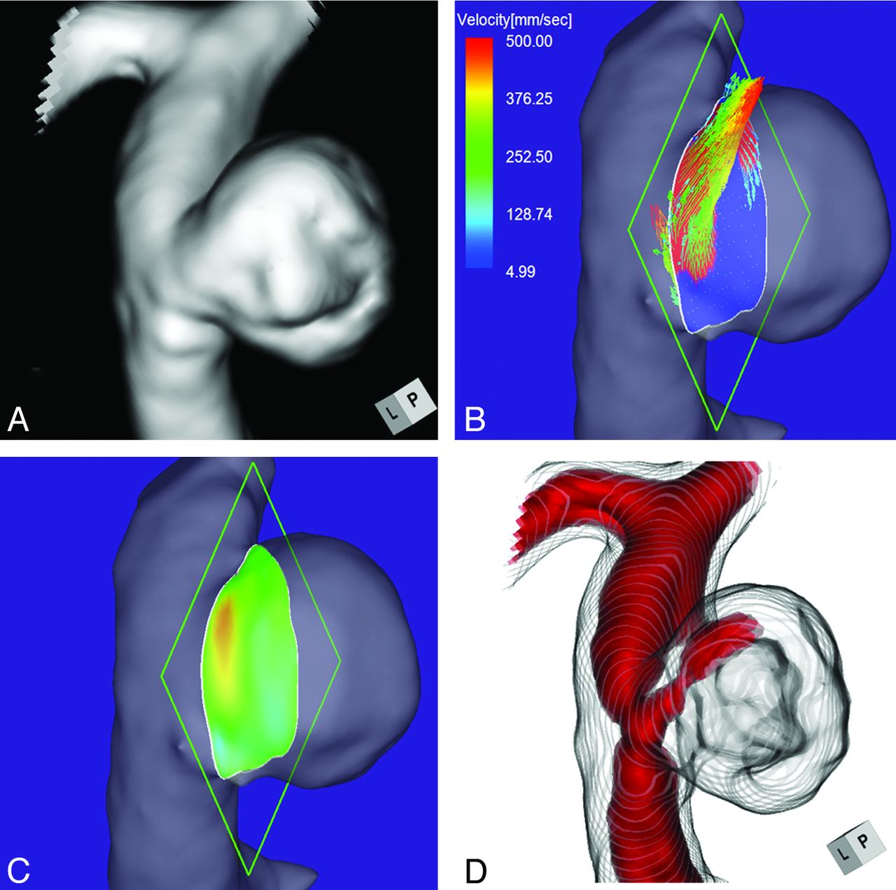
Case 1. A 75-year-old woman with an unruptured right ICA–posterior communicating artery bifurcation aneurysm. A, 3D TOF MRA image. B, 4D flow MR image demonstrates the inflow area (red) on the section plane and yields inflow velocity profiles. The angle of the section plane that determines the aneurysm orifice with respect to the imaging section direction on 3D TOF MRA is 73°. C, 4D flow MR image demonstrates the inflow zone (red). D, TC 3D MRA image depicts the putative inflow zone located on the distal neck. Red indicates the area where the MR signal intensity exceeded 375.
Case 2.
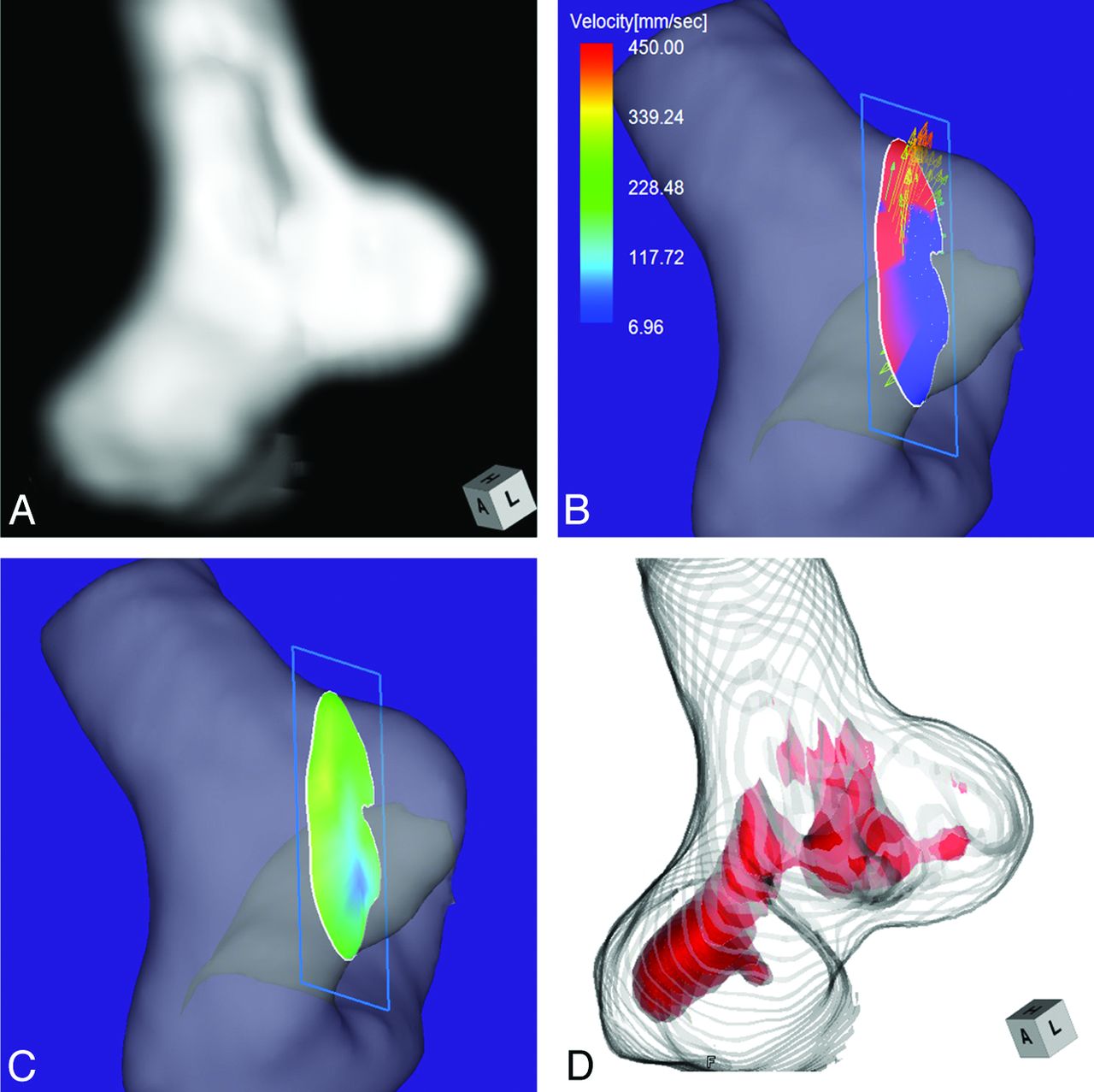
Case 2 was a 58-year-old woman with an unruptured multilobulated aneurysm at the left MCA bifurcation. The aneurysmal maximum diameter and neck measured 5.1 and 5.0 mm, respectively (Fig 3A). The angle of the section plane that identified the orifice with respect to the imaging section direction on 3D TOF MRA was 25°. 4D flow MR imaging showed that the inflow entered through the distal neck of the aneurysmal orifice (Fig 3B). The maximum inflow velocity was 301 mm/s. The inflow zone was located at the distal neck (Fig 3C). On TC 3D MRA images, the area with a signal intensity of >320 suggested that the inflow entered through the distal neck (Fig 3D). This aneurysm was recorded as a group 1 aneurysm.

Case 2. A 58-year-old woman with an unruptured multilobulated aneurysm at the left MCA bifurcation. A, 3D TOF MRA. B, 4D flow MR imaging demonstrates inflow entering through the distal neck of the aneurysmal orifice. The angle of the section plane that identifies the aneurysmal orifice with respect to the imaging section direction on 3D TOF MRA is 25°. C, 4D flow MR imaging demonstrates the inflow zone (red). D, TC 3D MRA depicts the putative inflow zone located on the distal neck. Red indicates the area where the MR signal intensity exceeds 320.
Case 3.
Case 3 was a 51-year-old woman who presented with a medially projecting unruptured aneurysm on the paraclinoid segment of the left ICA (Fig 4A). The maximum diameters of the aneurysm and the neck were 5.4 and 2.9 mm, respectively. The angle of the section plane that identified the aneurysmal orifice with respect to the imaging section direction on 3D TOF MRA was 56°. 4D flow MR imaging showed that the inflow entered through a small area on the distal neck (Fig 4B) where the inflow zone was located (Fig 4C); maximum inflow velocity was 285 mm/s. On TC 3D MRA images, color coding of the area with a signal intensity of >300 suggested that the inflow entered through the proximal neck and flowed along the aneurysm wall (Fig 4D). Because these findings suggested that the putative inflow zone was located on the proximal rather than the distal neck, this aneurysm was placed in group 2.

Case 3. A 51-year-old woman with a medially projecting unruptured aneurysm on the paraclinoid segment of the left ICA. A, 3D TOF MRA image. B, 4D flow MR imaging demonstrates flow entering through the distal neck. The angle of the section plane that identifies the aneurysm orifice with respect to the imaging section direction on 3D TOF MRA is 56°. C, 4D flow MR imaging shows the inflow zone (red). D, TC 3D MRA image depicts the putative inflow zone on the proximal neck. Red indicates the area where the MR signal intensity exceeds 300.
Case 4.
Case 4 was a 70-year-old man who presented with a medially projecting, unruptured aneurysm on the paraclinoid segment of the right ICA (Fig 5A). The maximum diameters of the aneurysm and neck were 3.6 and 4.0 mm, respectively. The angle of the section plane that identified the aneurysm orifice with respect to the imaging section direction on 3D TOF MRA was 65°. 4D flow MR imaging showed that the flow entered the aneurysmal lumen through an area along the distal margin of the neck (Fig 5B). The inflow zone was located on the distal neck (Fig 5C). The maximum inflow velocity was 406 mm/s. On TC 3D MRA images, color coding of the area with a signal intensity of >395 suggested that inflow entered through the proximal neck (Fig 5D). We posited that the putative inflow zone was located on the proximal rather than the distal neck and placed this aneurysm in group 2.

Case 4. A 70-year-old man with a medially projecting, unruptured aneurysm on the paraclinoid segment of the right ICA. A, 3D TOF MRA image. B, 4D flow MR image shows that the inflow enters through the area along the distal margin of the neck. The angle of the section plane that identifies the aneurysm orifice with respect to the imaging section direction on 3D TOF MRA is 65°. C, 4D flow MR imaging shows the inflow zone (yellow). D, TC 3D MRA image depicts the putative inflow zone on the proximal neck. Red indicates the area where the MR signal intensity exceeded 395.
Case 5.
Case 5 was a 65-year-old man with an unruptured lateral-projection aneurysm on the cavernous segment of the left ICA. The maximum diameters of the aneurysm and the neck were 7.3 and 6.8 mm, respectively (Fig 6A). The angle of the section plane that identified the aneurysm orifice with respect to the imaging section direction on 3D TOF MRA was 86°. By 4D flow MR imaging, the inflow entered through the lateral half of the aneurysmal orifice (Fig 6B). The inflow zone was located on the side lateral to the neck (Fig 6C). The maximum inflow velocity was 647 mm/s. However, on TC 3D MRA images, identification of the area with a signal intensity of >410 suggested that the putative inflow zone was located on the distal neck (Fig 6D). This aneurysm was assigned to group 3.

Case 5. A 65-year-old man with an unruptured aneurysm on the cavernous segment of the left ICA. A, 3D TOF MRA image. B, 4D flow MR image shows the inflow area (red) on the section plane and inflow velocity profiles. The angle of the section plane that identifies the aneurysm orifice with respect to the imaging section direction on 3D TOF MRA is 86°. C, 4D flow MR imaging shows the inflow zone (red). D, TC 3D MRA image depicts the putative inflow zone on the distal neck. Red indicates the area where the MR signal intensity exceeds 410.
Discussion
Graves et al9 studied a canine carotid aneurysm model and reported that aneurysms exhibited 3 distinct flow zones: an inflow zone, an outflow zone, and a central slow flow vortex. They stressed the importance of packing the inflow zone for successful aneurysm obliteration. Coils placed in the inflow zone block the impact exerted by the blood stream on the aneurysmal wall and induce thrombosis formation within the dome.9,15 After endovascular treatment, the water hammer effect of the blood flow results in coil compaction in the inflow zone and recanalization.10,15 Valencia et al14 observed high wall shear stress and increased pressure in the inflow zone; both are related to the regrowth and rerupture of cerebral aneurysms. Therefore, to obtain good treatment outcomes, one must identify the exact location of the inflow zone and evaluate the hemodynamics in this area.
During the coil embolization procedure, DSA may yield information on the temporally resolved hemodynamics and may help to identify the inflow zone. However, the information provided by this conventional method is limited. It cannot be used for the acquisition of quantitative variables of various hemodynamic parameters or of data at arbitrary time points in the cardiac cycle, and it is not 3D. Furthermore, DSA information can be affected by the speed or direction of the injected contrast medium and even by the mass effect of an inserted catheter.
4D flow MR imaging facilitates the direct, noninvasive measurement of the in vivo 3D blood flow and its velocity in the vascular region of interest.33⇓–35 Technologic advances in MR imaging have made it possible to assay the flow condition in aneurysms by 4D flow MR imaging.18,19 Both 4D flow MR imaging and computational fluid dynamics studies, used to evaluate the hemodynamics of cerebral aneurysms, returned similar results with respect to velocity distributions, inflow streamlines, and intra-aneurysmal flow patterns in human cerebral19,21,23 and experimental canine aneurysms.36 In addition, 4D flow MR imaging results were validated by computational fluid dynamics studies performed on a life-size human aneurysm phantom.37⇓–39 Moreover, previous studies confirmed the feasibility of depicting the aneurysmal inflow.18,20,23,26,27 Consequently, 4D flow MR imaging is the criterion standard for the identification of the inflow zone of cerebral aneurysms.
According to others,11,13,40 the inflow zone of lateral-projection aneurysms was located on the distal neck. However, in 6 of our 24 lateral-projection aneurysms (25%), it was found on the other side of the neck. Because these 6 aneurysms did not differ in their location and morphologic parameters from aneurysms whose inflow zone was on the distal neck, it is important to identify the exact location of the inflow zone even in lateral-projection aneurysms. The range of maximum inflow was very wide (285–922 mm/s). High inflow velocity might be a predisposing factor for coil compaction or recanalization after endovascular coil embolization.
We investigated whether TC 3D MRA represents a convenient alternative to 4D flow MR imaging for identifying the aneurysmal inflow zone. We found that in 64% of our aneurysms (group 1), the inflow zone identified on TC 3D MRA and 4D flow MR imaging coincided, while in 14%, especially in paraclinoid aneurysms, the 2 methods localized the inflow zone on opposite sides of the neck (group 2). To identify aneurysms whose inflow zone is reliably depicted on TC 3D MRA images without the aid of 4D flow MR imaging, we looked for factors that played a role in the consistency of findings made with TC 3D MRA and 4D flow MR imaging. Neither the aneurysm location, morphologic parameters, nor the MRA signal intensity of the inflow could predict the consistency.
The signal intensity of 3D TOF MRA is mainly affected by the flow velocity.41⇓⇓–44 In this study, the maximum inflow velocity in our group 2 aneurysms was significantly lower than that in group 1 (P = .029). The sensitivity of 3D TOF MRA, on the other hand, is affected by the direction of the blood flow.41⇓⇓–44 We measured the angle of the section plane that identified the aneurysm orifice with respect to the imaging section direction on 3D TOF images. This angle was significantly smaller in group 1 than in group 3 aneurysms (P = .045). In 10 of 11 aneurysms (91%) whose angle ranged from 0° to 29°, the inflow zone was at a similar location on 4D flow MR imaging and TC 3D MRA studies. In the remaining aneurysm, 3D TOF MRA failed to depict the putative inflow zone. Our findings suggest that if 3D TOF MRA can depict the putative inflow zone in aneurysms whose neck has a section plane angle below 30° with respect to the imaging section direction, the information it yields is very precise. Concentric flow conditions such as slow or turbulent flow may lead to a regional elimination of TOF signal intensities,41⇓⇓–44 and this may result in misidentification of the inflow zone on 3D TOF MRA images. However, in this study, no aneurysms were excluded due to signal loss when estimating the inflow zone and measuring morphologic parameters. Moreover, in conjunction with interpolation methods for 3D TOF MRA, the voxel dimensions may affect TOF signal intensities.42⇓–44 Further studies are needed to improve the accuracy of 3D TOF MRA results,.
Our study has some limitations. First, because most of the aneurysms were part of a long-term follow-up study, many of the included small and wide-neck aneurysms were not candidates for endovascular coil embolization. Second, for 4D flow MR imaging to evaluate the inflow zone, we used a section plane that corresponded to the aneurysm orifice. This rendered difficult the 4D flow MR imaging of cerebral aneurysms whose neck configuration was complicated, and such aneurysms were excluded from the present study. Third, the spatial resolution of both 4D flow MR imaging and 3D TOF MRA is limited. Although we expected the visibility of the inflow zone of small aneurysms to be poor on both types of study, there was no significant difference in our ability to identify the inflow zone in groups categorized by the maximum diameter of the aneurysm (data not shown). On 4D flow MR images, the spatial averaging effect and the partial volume effect may result in incorrect flow estimation.18 To evaluate the flow condition in aneurysms with a minimum diameter of 2.0 mm, a spatial resolution of 0.5 mm in the isotropic voxel dimensions may be desirable.37 Because the number of aneurysms included in this study was relatively small, larger series are needed to identify the role of aneurysmal size.
Conclusions
We recommend that before endovascular coil embolization, the exact location of the inflow zone be identified, even in lateral-projection aneurysms. 4D flow MR imaging can demonstrate the inflow zone and provide inflow velocity profiles. In aneurysms whose neck section plane angle is <30° with respect to the imaging section direction on 3D TOF MRA images, TC 3D MRA may depict the inflow zone reliably. Further studies on the hemodynamics of the inflow zone are needed to clarify the mechanisms of coil compaction or recanalization in patients with cerebral aneurysms treated by endovascular coil embolization.
Acknowledgments
We are grateful to Professor Jun-ichiro Hamada for his encouragement and his dedication to our work. We mourn his untimely death. We thank Aki Watanabe, MR application specialist, Application Department, Siemens Japan, Tokyo, Japan, for technical advice, and Keiko Sumita, RT, and Takamitsu Matsuzaki, RT, of the Department of Radiation Technology, Mattoh-Ishikawa Central Hospital, Hakusan, Japan, for their dedicated support in performing this study.
References
- Received August 27, 2013.
- Accepted after revision December 16, 2013.
- © 2014 by American Journal of Neuroradiology


Jump to section
Related Articles
Cited By...
- Large Neck and Strong Ostium Inflow as the Potential Causes for Delayed Occlusion of Unruptured Sidewall Intracranial Aneurysms Treated by Flow Diverter
- Inflow Jet Patterns of Unruptured Cerebral Aneurysms Based on the Flow Velocity in the Parent Artery: Evaluation Using 4D Flow MRI
- Three-dimensional printing of anatomically accurate, patient specific intracranial aneurysm models
- Parent Artery Curvature Influences Inflow Zone Location of Unruptured Sidewall Internal Carotid Artery Aneurysms