Article Text

Abstract
Background Many cerebral aneurysms can be treated effectively with intracranial stents. Unfortunately, stents can occlude perforating vessels near the treatment site which can decrease cerebral perfusion and increase the risk of stroke.
Methods Particle image velocimetry was used to investigate the effects of intracranial stents on flows in perforators near a treated aneurysm. In Phase 1 of the study, different stent configurations were deployed into an idealized physical model of a sidewall aneurysm with perforating vessels. The configurations investigated were the Pipeline embolization device (PED) and one, two and three telescoping Neuroform stents. In Phase 2 of the study a single Neuroform stent was deployed so that the stent struts directly occluded the perforating vessel.
Results In Phase 1 of the study it was found that even three telescoping stents affected perforating vessel flow less than a single PED under pulsatile conditions (average reduction 32.7% vs 46.5%). Results from Phase 2 indicated that the location of the occluding strut across the perforating vessel orifice had a greater impact on perforating vessel flow than the percentage occlusion.
Conclusion The findings of this study show that the use, configuration and positioning of intracranial stents can all have considerable influence on flow in affected perforating vessels near treated cerebral aneurysms.
Statistics from Altmetric.com
Introduction
Cerebral aneurysms occur in an estimated 6% of the world's population.1 When they rupture, cerebral aneurysms are lethal in nearly 50% of cases.2 Accordingly, treatments that prevent rupture by eliminating flow into and out of the aneurysmal sac are critically important to global health. Endovascular treatments such as coil embolization have been used more frequently in recent years because they are less invasive than surgical techniques and also because they are more effective.3–5 Unfortunately, recurrence rates for large aneurysms can be as high as 50% after embolic coling.6 Such frequent recurrence demonstrates a clear need for improved coil embolization techniques and/or for other endovascular approaches to cerebral aneurysm treatment.
One way to improve coil embolization is to use a stent as a support structure for deployed coils. In fact, expanded clinical use of stent-assisted coiling has led to markedly decreased aneurysmal recurrence over the past decade, especially for wide-neck aneurysms.7 As new and improved designs are being developed, one characteristic that is critically important in most, if not all, applications of stents is porosity (defined as the fraction of metal-free area per total surface area covered by a stent). The porosity of a stent directly affects the amount of flow that enters an aneurysm or perforating vessel covered by the stent. Studies have found that lower porosity stents lead to greater flow reductions within aneurysms.8 ,9 To reduce stent porosity across the aneurysm (using high-porosity flexible stents), many clinicians use a stent-within-a-stent technique or ‘telescoping’. Telescoping comprises the sequential deployment of additional high-porosity stents inside of an initial high-porosity stent in order to increase metal coverage at the aneurysm and thereby reduce effective porosity. Low-porosity stents have been found to be safe for clinical use;10 however, understanding of the specific hemodynamics they affect is limited.11 Further, there is well-justified clinical concern that low-porosity stents may decrease cerebral perfusion and increase risk of stroke when they are deployed across perforating vessels in the brain.12 An image showing the deployment of a stent across an aneurysm is presented in figure 1.
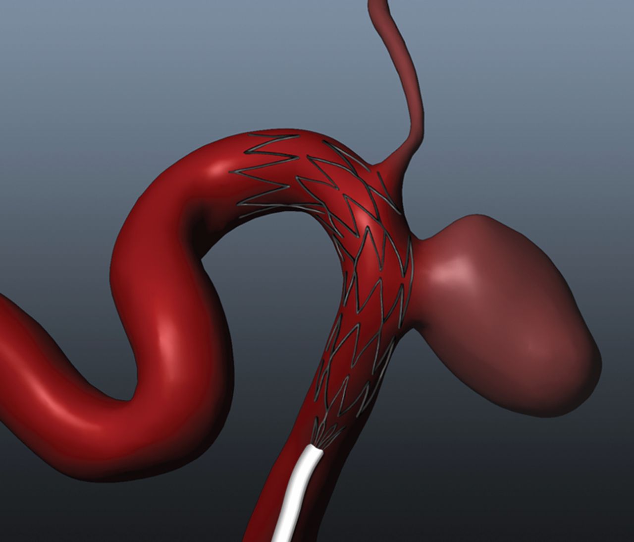
Rendering of a low-porosity stent deployed into a computational anatomical model. The stent placement is across the perforator ostia which could lead to possible flow interference through the vessel.
Since FDA approval in 2010, the low-porosity Pipeline embolization device (PED) has been used regularly to treat cerebral aneurysms, which has stimulated considerable interest in the clinical community.13 Interest in the device stems from its potential to regulate aneurysmal fluid dynamics, thereby facilitating thrombus formation, vascular remodeling and aneurysmal elimination. Important related questions are whether similar treatment effects can be achieved by telescoping higher porosity stents until a lower effective porosity is achieved, and the levels of decreased perfusions that can result in either case when low-porosity perforating vessel coverage results near the treatment site. This study presents experimental and simulated data that address both questions.
Experimentation and simulation have both been used before to examine fluid dynamics in cerebral aneurysm models treated with intracranial stents. However, previous studies dealing with multiple stent deployments have focused almost exclusively on flow within aneurysms.14–16 In contrast, the primary focus of this study is flow in perforating vessels. Stereo particle image velocimetry (PIV) is used to quantify flows in an idealized perforating vessel (and aneurysm) before and after different intracranial stent treatments. In Phase 1 of the study, global effects of the PED and one, two and three telescoping Neuroform stents (Stryker, Freemont, California, USA) were examined experimentally and compared. In Phase 2 of the study, more detailed local flow effects of stent strut placement at the perforating vessel orifice were analyzed both experimentally and with computational fluid dynamics (CFD).
Materials and methods
Modeling
An idealized model of a sidewall aneurysm and perforator vessels was designed based on in vivo angiographic images. A computational model of the geometry was developed in SolidWorks (SolidWorks, Concord, Massachusetts, USA) with a parent vessel diameter of 3.0 mm and an upstream perforating vessel diameter of 1.2 mm (to simulate the ophthalmic choroidal artery), as shown in figure 2. The computational model was used to create a physical core model of pot metal using computer numerical controlled cutting. Sylgard 184 silicon elastomere (Dow Corning, Midland, Michigan, USA) was molded around the metal core model, which was then melted out, leaving an optically clear model to be used for experiments.
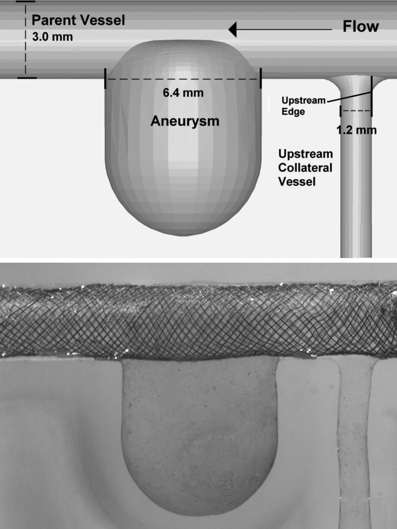
Computational idealized sidewall aneurysm model including perforating vessel (top). Physical model with the Pipeline embolization device deployed across the aneurysm and the perforator (bottom).
Device deployment
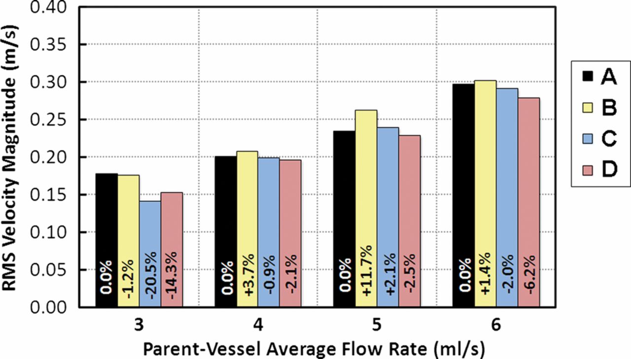
This study was performed in two phases. Phase 1 examined four different stent treatments: sequential telescoping of low-porosity Neuroform stents across the aneurysm (one, two and three high-porosity stents) and deployment of a single PED (Chestnut Medical, Menlo Park, California, USA). An untreated case was also run for comparison. Each stent was placed across the aneurysm and perforator vessel, as shown in figure 2. Phase 2 of the study examined four different deployments across the perforator vessel. Photographs taken looking up the perforator vessel (down-the-barrel view) from the parent vessel of the model were used to assess stent strut placements quantitatively, as shown in figure 2. For each deployment, the location of the center of mass of the stent strut was calculated as a percentage from the upstream edge of the vessel, where 100% corresponded to the downstream edge. MATLAB was used to determine the percentage coverage of each placement by calculating the percentage of pixels at the orifice of the perforator that were covered by the strut. The percentage coverage was then determined by dividing the number of pixels of the strut by the total number pixels of the perforator vessel. The stent deployments investigated were: (A) untreated; (B) stent located 100% downstream with an occlusion of 0%; (C) stent located 50% downstream with an occlusion of 26%; and (D) stent located 25% downstream with an occlusion of 7%. Deployment parameters and images for Phase 2 of the study are presented in table 1.
Deployment parameters and images for Phase 2 of the study
Particle image velocimetry (PIV)
During the experiments the model was attached to flexible polyvinyl chloride tubing and connected to a Compuflow 1000 piston pump (Shelley Medical, Toronto, Ontario, Canada). Pulsatile flow conditions, employing a vertebral flow waveform, were examined at four flow rates (3, 4, 5 and 6 ml/s) to simulate a physiologic range of normal and diseased conditions.17 The blood analog solution comprised water, aqueous sodium iodide and glycerol and maintained a refractive index of 1.43, the same as that of Sylgard 184, and a viscosity of 3.16 cP.
PIV was performed using a Flowmaster 3D stereo PIV system (LaVision, Ypsilanti, Michigan, USA), which included a Solo PIV III dual cavity pulsed YAG laser with a 532 nm wavelength (New Wave Research, Fremont, California, USA) and two Imager Intense cross-correlation CCD cameras. The working fluid was seeded with 8 μm fluorescent particles (Thermo Scientific, Waltham, Massachusetts, USA), which were illuminated with a 0.5 mm thick laser sheet. Low-pass optical filters with a 572 nm cutoff (Omega Optical, Brattle Bro, Vermont, USA) were installed on the cameras to allow the particles to be imaged despite laser reflections from the stent.
Two hundred image pairs were acquired across a single plane taken at the center of the aneurysm and perforator. From the acquired images, velocity vectors were calculated using a cross-correlation algorithm within DaVis software (Lavision, Ypsilanti, Michigan, USA). The velocity vectors were averaged over the 200 image pairs to form a single velocity flow field for each flow rate. The root mean square velocity magnitude (V
RMS) was then calculated within the aneurysm and within the perforator. The equation used was as follows:
where n is the number of data points within the aneurysm or perforator vessel and Vi is the flow velocity magnitude at point i. The use of this equation for PIV is explained fully by Babiker et al.18 For the aneurysm, V RMS represents the overall velocity magnitude within the aneurysmal volume, where a reduction in velocity magnitude is analogous to a reduction in overall fluid dynamic activity within the aneurysm. For the perforator vessel, V RMS is proportional to velocity magnitude along the vessel axis (which is proportional to volume flow rate). This means that a reduction in V RMS across the perforator domain corresponds to a reduction in flow through the perforator vessel.
Computational fluid dynamics (CFD)
CFD simulations were also conducted to investigate the effects of strut placement on perforator flow (by varying the placement of a Neuroform stent strut across the perforator orifice). The Neuroform strut was approximated as 40 µm thick bar. The strut was created in ANSYS ICEM 12.1 software (ANSYS, Canonsburg, Pennsylvania, USA). The strut was placed across the perforator orifice (perpendicular to the flow direction) in the computational model at 20%, 40%, 60% and 80% downstream from the upstream edge. The computational geometries of the strut and perforator vessel were meshed using ANSYS ICEM 12.1 software. A mesh density function was prescribed near the volume around the stent struts. The OCTREE method was then used to generate approximately 3 300 000 tetrahedral mesh elements (corresponding to 560 000 nodes) for the vessel lumen and strut volume in each stent placement case. CFD simulations were conducted in ANSYS Fluent 12.1 software (ANSYS Fluent, Lebanon, New Hampshire, USA). The vessel walls and strut volume were assumed to be rigid, and a no-slip boundary condition was imposed at the boundaries of the vessel and strut walls. The fluid volume was approximated as an incompressible fluid with the same viscosity and density as the blood analog solution used in in vitro experiments. Steady laminar flow profiles with 3 ml/s flow rates were prescribed at the inlets and zero pressure boundary conditions were prescribed at the outlets. Fluid dynamic simulations were conducted using a second-order upwind scheme for momentum and the SIMPLE algorithm was used to define the pressure-velocity coupling.
Results
Effects of stents on aneurysmal flows
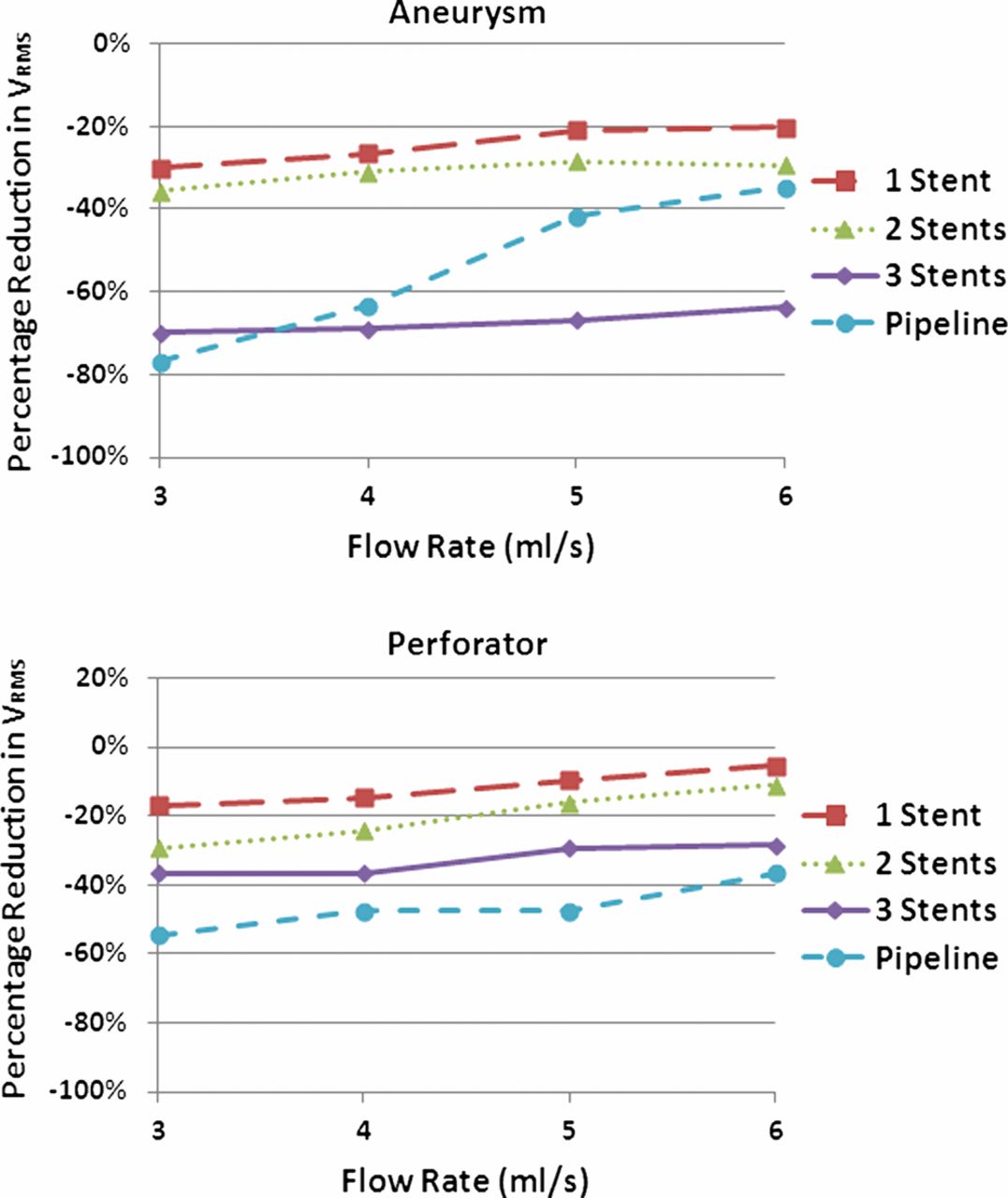
The results are presented in figure 3 as line graphs comparing the percentage reduction in V RMS within the aneurysm or within the perforator to the untreated case. With high-porosity stents, fluid dynamic activity within the aneurysm was reduced after each sequential stent deployment. The greatest percentage reductions were observed after the first and third stent deployments, with an average reduction of 24% after the first deployment and an additional reduction of 36% after the third deployment. Reductions between the first and second stent placement were lower, with an average reduction of 7%. The PED led to reductions comparable to those for two and three sequentially placed stents: an average of 54% total reduction was observed for the PED.

Post-treatment reductions in aneurysmal (top) and perforator (bottom) root mean square velocity (V RMS). Note that, in most cases, three telescoping Neuroform stents reduced aneurysmal V RMS most and the Pipeline embolization device reduced perforator V RMS most.
Effects of stents on perforator flows
V RMS in the perforator vessels followed similar trends to aneurysmal V RMS after telescoping stent treatment. As shown in figure 3, the placement of each stent across the upstream vessel led to greater V RMS reductions in each case. In contrast to the aneurysmal data, perforator V RMS reductions were more consistent with each stent placement, ranging between 10% and 20% for most cases. The PED led to the greatest reductions in V RMS of any treatment, with an average of 47%.
Effects of stent strut placement on perforator flows
Figure 4 illustrates the V RMS through the perforator vessel for each case investigated, as well as percentage changes from the untreated case. Occlusion by the stent (deployments C and D) led to a reduction in perforator V RMS. Deployment B (100% downstream, 0% occlusion) led to an increase in perforator V RMS compared with the untreated case. With one exception at the 3 ml/s parent vessel flow rate, the results showed that deployment D (25% downstream, 7% occlusion) led to greater perforator V RMS reductions than deployment C (50% downstream, 26% occlusion).

Post-treatment reductions in perforating vessel root mean square velocity (V RMS) for the different stent strut placements described in table 1. Note that V RMS varies consistently with respect to strut location rather than the degree of perforating vessel orifice occlusion.
Discussion
Intracranial stents have been shown to help reduce flow into cerebral aneurysms and successfully occlude them from circulation.7 However, an unfortunate consequence of treatment with stents is decreased perforating vessel flow. The results presented in this study show that stent placement reduces flow through perforator vessels. Further, the porosity of the stent configuration, the type of stent used and the placement of the stent struts all affect flow through the perforator.
Effects of stents on aneurysmal flow
The changes in fluid dynamic activity observed within the aneurysm were in agreement with previous studies that examined multistent placements. Specifically, a PIV study by Canton et al concluded that sequential placement of stents led to a decrease in fluid dynamic elements that may lead to rupture, including vorticity strength and wall shear stresses.14 Our results agree, showing that there was a reduction in the V RMS within the aneurysm. The non-linear pattern in the flow reduction found with sequential stent placement was also consistent with previous studies.14 ,16 The differences in V RMS reductions after each stent placement may also relate to the alignment of the struts of the respective stents. Because the alignment of the struts was not specifically regulated (except to ensure that the struts were not perfectly overlapped along the long axis), the positioning of the struts within the telescoping configuration may have influenced the fluid dynamic activity within the aneurysm. Specifically, differences in relative strut position could lead to local flow effects near the aneurysmal entrance that effect changes in aneurysmal fluid dynamic activity.
The PED led to V RMS reductions comparable to those for multistent deployments, indicating that it reduced fluid dynamic activity within the aneurysm more effectively by itself. This finding is in agreement with a review of the PED which concluded that the device was more effective at reducing mass effect as a stand-alone device than high-porosity flow diverters.19 A more comprehensive study of the PED and telescoping stents is currently underway; however, observations from this study provide a useful starting point for comparison. While observing fluid dynamic activity within the aneurysm was not the main goal of this study, the agreement of our findings with previous studies indicates that our experiments accurately represent aneurysmal fluid dynamic activity which, in turn, supports the results we observed in perforator vessels.
Effects of stents on perforator flows
The reductions in V RMS across the perforator vessel domains with sequential telescoping stent placement were consistent with observations from the aneurysm. However, while reductions in V RMS contribute to aneurysmal occlusion, for the perforator vessels, similar V RMS reductions may lead to inadequate circulation or even to occlusion of vessels. While clinical studies have shown that in general the use of intracranial stents is safe, these studies focused on single stent placements.10 Our results agree with previous in vitro studies which found that high-porosity stents have a flow reduction at or below 15% through the perforator vessel for a single stent deployment.20 However, we also found that the reduction in porosity which occurs when three stents are deployed telescopically can lead to reductions in V RMS through perforator vessels ranging from 27% to 46% across parent vessel flow rates. These reductions in flow through the perforator vessel are 20% higher than those observed with the use of a single stent. Such a difference indicates that the use of multiple stents could increase perforator occlusion.
The PED device led to perforator V RMS reductions greater than those for three telescoping stents. As discussed by Fiorella et al, flows into the aneurysm and perforator vessels are governed by different hemodynamics and devices such as the PED are designed to have a greater effect on aneurysmal flow.19 Our results agree that fluid dynamics within the aneurysm are more affected than perforator flow by the PED, except at higher flow rates where very similar reductions were observed. Previous in vivo studies have shown that a reduction in perforator flow greater than 50% can result in complications including loss of patency of the perforating side branches and increased risk of infarction or ischemia.21 Unfortunately, for all flow rates (except 6 ml/s), the PED led to V RMS reductions near or at 50% in the perforator vessel. While the V RMS reductions are not exactly the same as the physiological flow rate reductions that would be observed clinically, the reduction in the V RMS observed implies that the superior reduction in aneurysmal fluid dynamic activity associated with PED treatment may also lead to unwanted complications relating to perforating vessels. The relationship between flow diverting devices and perforator vessels across which they may be deployed is important when considering the development of new low-porosity stents which have a higher stent strut density.
Effects of stent strut placement on perforator flows
A correlation between the placement of a stent strut across the perforator vessel and V RMS in the vessel was observed, but the results were contrary to initial expectations. As shown in figure 4, V RMS decreased as predicted for the occluded cases (C and D) compared with the untreated (A) and 0% occluded (B) cases. At 0% occlusion (B), V RMS was greater than in the untreated case (A) for all but the 3 ml/s flow rate. Because the stent was specifically placed to achieve 0% occlusion, this may have led to a hemodynamic change that actually directed flow to the perforator. Similar observations were made in a CFD study by Kim et al which found that single stent placement across an aneurysm led to varied hemodynamic changes based on geometry, and that the change in aneurysmal inflow rate after single stent placement was unremarkable in comparison with the untreated case.16
The intuitive hypothesis about stent strut placement is that the greatest V RMS reduction would coincide with the largest degree of occlusion; however, our results show that there was a greater V RMS reduction within the perforator vessel at 7% occlusion (D) than at 26% occlusion (C). Rather than varying with degree of occlusion, the V RMS reduction correlated to the position of the center of mass of the strut relative to the perforator ostium. At a flow rate of 3 m1/s, greater flow was observed for 7% occlusion (D). However, we feel that this was simply an anomaly at a very low flow rate.
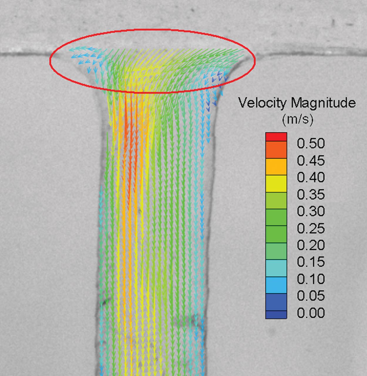
It has previously been shown that local flow disturbances caused by stent struts result in low wall shear stress and recirculating flows.22–24 Local flow disturbances induced by stents eventually return to normal flows with large stent strut spacing corresponding to more rapid flow restoration.23 Since flow eventually recovers downstream of stent struts, it can be inferred that the position of the strut relative to the perforator (along the axis of fluid flow) may have a significant effect on percentage reductions in perforator V RMS. This effect was observed in the results from the CFD simulations where the position of the Neuroform strut had a large effect on perforator flow. The placement of the Neuroform strut closer to the upstream tip of the perforator orifice induced flow disturbances that led to the largest reduction in perforator flow, as shown in figure 5. Placing the strut further downstream from the tip of the orifice reduced flow disturbances and their effects on perforator flow. As shown in figure 6 where a velocity field from the PIV data is shown, the inlet jet to the perforator enters from the upstream side of the vessel, indicating that placement of the strut in this location would lead to greater disturbances, which also agrees with the CFD simulations presented in figure 5. Our collective results support the view that strut placement may be as important as porosity when considering effects on perforator vessel flows. It is understandable that, although the placement of struts may play an important role in local hemodynamic effects, their exact placement in a desirable position may not be possible in practice. However, as placement capabilities improve, the effects we have documented could become useful for optimizing device deployments.
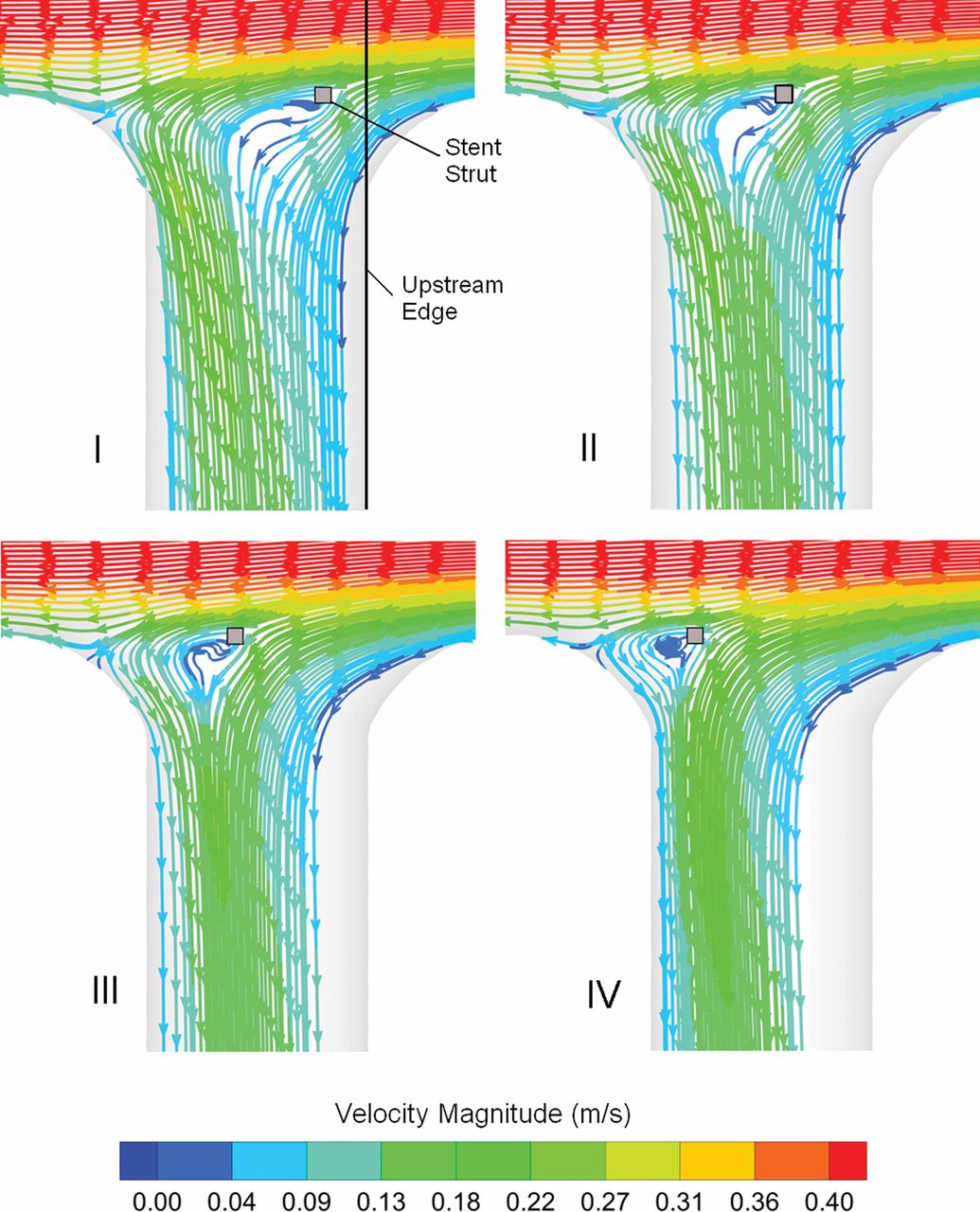
Simulated flows through the perforating vessel with a stent strut at 20% (I), 40% (II), 60% (III) and 80% (IV) from the upstream edge of the vessel. Note that the further upstream the strut, the more it disturbs perforating vessel flow.

Measurement of flow through the untreated perforating vessel by particle image velocimetry (PIV) for a 6 ml/s steady parent vessel flow rate. Note the high-velocity jet within the perforating vessel that originates from the upstream edge of the vessel orifice. PIV resolution was actually twice that shown (a vector skip was needed to make the flow map more clearly visible). The circled area highlights the vectors at the perforator entrance where local flow effects were affected by stent placement.
Limitations to this study stem from assumptions made during experimentation, including the use of an idealized model and limited flow conditions and stent deployment geometries. Because the purpose was to observe general trends between stent deployments (rather than patient-specific conditions), an idealized model obtains this goal because it is based on averaged anatomical geometries. While these types of studies can lead to an unlimited number of conditions, the ones selected represent a good range of the conditions seen in these types of aneurysms and allow for an accurate assessment of trends.
Conclusion
The deployment of both high- and low-porosity stents to treat cerebral aneurysms had a significant effect on flow through nearby perforating vessels. Sequential telescoping deployments (which led to decreased effective porosity) significantly reduced perforator V RMS (which may increase the risk of stroke). The placement of a low-porosity stent, the PED, led to even greater V RMS reductions across the perforator. Further, the location of stent struts affected local hemodynamics at the vessel orifice, leading to changes in flow through the perforator. Because these studies were the first to experimentally evaluate the effects of multiple stent deployments and strut placement on perforator vessel flows, there is a great deal of room for further exploration. Future research goals include evaluating different flow diverters and their effects on perforator vessels, observing the effects of relative stent strut alignments between telescoping placements and focusing more on local effects of stent struts since these proved important in this study.
References
Footnotes
-
Contributors All authors contributed to the development, data collection and/or data analysis of the study and all authors contributed to the final paper by either writing or editing.
-
Funding This work was supported in part by the following sources: Brain Aneurysm Foundation Research Grant, Women and Philanthropy Society Category B Grant, American Heart Association Beginning Grant in Aid and National Science Foundation CAREER Award.
-
Competing interests None.
-
Patient consent Not obtained.
-
Provenance and peer review Not commissioned; externally peer reviewed.
-
Data sharing statement All data collected are available to anyone who would like to see the images or numbers by contacting the corresponding author.
-
Correction notice This article has been corrected since it was published Online First. The author name Fernando Gonzalez has been amended to L Fernando Gonzalez.