
Abstract
BACKGROUND AND PURPOSE: 3D high-resolution MR imaging can provide reliable information for defining the exact relationships between the intraparotid facial nerve and adjacent structures. The purpose of this study was to explore the clinical value of using a surface coil combined with a 3D-PSIF-DWI sequence in intraparotid facial nerve imaging.
MATERIALS AND METHODS: Twenty-one healthy volunteers underwent intraparotid facial nerve scanning at 3T by using the 3D-PSIF-DWI sequence with both the surface coil and the head coil. Source images were processed with MIP and MPR to better delineate the intraparotid facial nerve and its branches. In addition, the SIR of the facial nerve and parotid gland was calculated. The number of facial nerve branches displayed by these 2 methods was calculated and compared.
RESULTS: The display rates of the main trunk, divisions (cervicofacial, temporofacial), and secondary branches of the intraparotid facial nerve were 100%, 97.6%, and 51.4% by head coil and 100%, 100%, and 83.8% by surface coil, respectively. The display rate of secondary branches of the intraparotid facial nerve by these 2 methods was significantly different (P < .05). The SIRs of the intraparotid facial nerve/parotid gland in these 2 methods were significantly different (P < .05) at 1.37 ± 1.06 and 1.89 ± 0.87, respectively.
CONCLUSIONS: The 3D-PSIF-DWI sequence combined with a surface coil can better delineate the intraparotid facial nerve and its divisions than when it is combined with a head coil, providing better image contrast and resolution. The proposed protocol offers a potentially useful noninvasive imaging sequence for intraparotid facial nerve imaging at 3T.
ABBREVIATIONS:
- FIESTA
- fast imaging employing steady-state acquisition
- MIP
- maximum intensity projection
- MPR
- multiplanar reconstruction
- PSIF
- reversed fast imaging with steady-state precession
- SIR
- signal-intensity ratio
3D high-resolution MR imaging can provide reliable information for depicting normal intraparotid facial nerve anatomy and defining the exact relationship of the intraparotid facial nerve and adjacent structures; this information could assist in the planning of parotid tumor surgery.1 Imaging the intraparotid course of the facial nerve is a challenge due to the fine structure and complex anatomy of the nerve.1⇓⇓–4 With recent advances in MR imaging technology, especially the use of surface coils combined with 3D high-resolution MR imaging technology, increased attention has been directed to intraparotid facial nerve imaging.1⇓⇓–4 The inherent resolution of a surface coil itself is significantly better than that of a head coil, ensuring high-quality imaging for fine structures, particularly in superficial organs such as the parotid gland or eye.1,5 Recently, 3D high-resolution sequences such as 3D gradient-recalled acquisition in the steady state sequence and 3D FIESTA have been applied to intraparotid facial nerve imaging.2⇓–4 These sequences rely mainly on the fat within the parotid gland as a high signal background to show the facial nerve because both the intraparotid facial nerve and the parotid duct are visualized as linear structures of low intensity.2⇓–4 In another report, the intraparotid facial nerve showed low signal compared with the high intensity of the parotid duct by using a balanced turbo-field echo, thus avoiding confusion between these 2 structures; however, no volumetric images were obtained,6 and MPR or curved planar reconstruction was not available. Thus, although there are several MR imaging sequences that can delineate the intraparotid facial nerve and parotid duct, limitations remain. The aim of this study was to explore the capabilities of simultaneously displaying the intraparotid facial nerve and parotid duct by using a surface coil combined with 3D-PSIF-DWI on a 3T MR imaging scanner.
Materials and Methods
Subjects
Twenty-one healthy volunteers (13 men, 8 women; age range, 24–58 years; mean age, 39.4 ± 11.7 years) were enrolled in our study. Our institutional ethics committee approved this study, and written informed consent was obtained from all subjects.
MR Imaging Technique
All scanning was performed on a 3T MR imaging scanner (Magnetom Trio-Tim; Siemens, Erlangen, Germany) by using a standard head and neck coil, followed by a surface coil. The scan ranged from the inferior orbital rim to the lower edge of the mandible. After conventional axial T1- and T2-weighted spin-echo imaging was completed, the 3D-PSIF-DWI sequence was performed. Parameters were as follows: T1WI: TR/TE, 520/15 ms; T2WI: TR/TE, 4000/80 ms; thickness, 3 mm; FOV, 240 × 240 mm; 3D-PSIF-DWI: TR/TE, 9.3/4.2 ms; thickness, 0.6 mm; FOV, 220 × 220 mm; flip angle, 35°; matrix size, 256 × 256; bandwidth, 446 Hz; spatial resolution, 0.6 × 0.6 × 0.6 mm; number of 3D partitions, 288; diffusion moment in the readout direction, 40 mT/m(*)msec; number of acquisitions, 1; acquisition time, 6 minutes 45 seconds.
All volunteers then underwent a right parotid gland sagittal scan with the 3D-PSIF-DWI sequence by using a 4-cm-diameter surface coil (3T Loop, 4 cm; Siemens). The coil was placed directly on the skin and was centered on the parotid gland. In addition, the coil plane should be in parallel with the z-axis of the magnetic field. 3D-PSIF-DWI parameters for this scan were the same as above, with the following changes: FOV, 100 × 100 mm; bandwidth, 229 Hz; number of 3D partitions, 88. Spatial resolution was altered in the following manner: 0.6 × 0.6 × 0.6 mm (group 1), 0.5 × 0.5 × 0.5 mm (group 2), and 0.4 × 0.4 × 0.4 mm (group 3). The acquisition times were 7 minutes 31 seconds, 9 minutes 27 seconds, and 14 minutes 5 seconds, respectively.
Postprocessing included MPR and MIP to better display the intraparotid facial nerve. The images obtained by these 2 methods were analyzed and compared according to Gray's Anatomy for Students by 2 neuroradiologists.7 If there was initial disagreement, a consensus was reached after discussion.
The display rates of the main trunk, first branches of the intraparotid facial nerve (cervicofacial division, temporofacial division), and secondary branches (temporal, zygomatic, buccal, marginal mandibular, cervical) by head coil and surface coil were calculated separately.
Quantitative Image Measurement
SNR Measurement.
The SNR was calculated by the following equation:
 where SIfn indicates the signal intensity of the facial nerve, and SIbg, the signal intensity of background.
SIR Measurement.
The SIR between the facial nerve and parotid gland on the same section is expressed as
 where SIfn indicates the signal intensity of the facial nerve, and SIp, the signal intensity of parotid gland.
Similarly, the SIR between the parotid duct and parotid gland on the same section is expressed as
 where SIpd indicates the signal intensity of the parotid duct, and SIp, the signal intensity of parotid gland.
For the quantitative measurement mentioned above, a round ROI was placed on the intraparotid facial nerve within a 1- to 2-cm range just after the facial nerve enters the parotid gland. The diameter of the ROI should not exceed the scope of the facial nerve or parotid duct. A same-sized ROI was also placed on the parotid gland to measure signal intensity while avoiding peripheral vasculature and artifacts. The ROI of the background was also selected on a corresponding section. Similarly, the SNR (parotid gland/background) and the SIR value (SIfn/SIp and SIpd/SIp) among the 3 different spatial resolutions were also recorded and analyzed.
The number of main trunks, first branches, and second branches displayed by these 2 methods was analyzed by using the χ2 test in the Statistical Package for the Social Sciences, Version 13.0 (SPSS, Chicago, Illinois). SIR and SNR were compared by using the t test, and a P value < .05 was considered a statistically significant difference.
Results
Image Interpretation of the Parotid Region
A water-selective excitation technique by 3D-PSIF-DWI was used to achieve uniform fat suppression. The fat component within the parotid gland was suppressed, so it appeared hypointense and adjacent muscle appeared isointense. The intraparotid facial nerve appeared as a linear structure of higher signal intensity than the parotid gland and muscle but slightly lower than the parotid duct. Arteries showed flow void while the signal intensity of veins was variable, being isointense, slightly hyperintense, or hyperintense according to different flow rates. Lymph nodes demonstrated higher signal intensity than the parotid parenchyma.
Nerve Display Rate between the Head Coil and Surface Coil
The display rates of the main trunk, first branches, and secondary branches of the intraparotid facial nerve with the head coil were 100%, 97.6%, and 51.4%, respectively, while for the surface coil, the display rates were 100%, 100%, and 83.8%, respectively (Table 1). There were no significant differences between the head coil and surface coil in displaying the main trunk and first branches of the intraparotid facial nerve, but a significant difference was found in the display rate of secondary branches by these 2 methods (P < .05) (Fig 1).
The branch numbers of the intraparotid facial nerve displayed by head and surface coils

A–C, 3D-PSIF-DWI with a head coil. A, Oblique sagittal MPR image of 1 volunteer shows the main trunk of the intraparotid facial nerve as a linear structure of high signal intensity compared with the parotid gland (arrow). The SIR is 1.32 ± 0.96. The margin of the distal part of the cervicofacial division is a little bit coarse. B, Oblique sagittal MIP image shows the main trunk of the intra-parotid facial nerve and cervicofacial division. C, Oblique coronal MIP view also displays the main trunk of the intra-parotid facial nerve and cervicofacial division. D and E, The same volunteer with a surface coil. D, 3D-PSIF-DWI image demonstrates the main trunk of the intraparotid facial nerve and cervicofacial division as high intensity, and the SIR was 1.78 ± 1.04. There is an increase in contrast between the facial nerve and the parotid gland compared with A. E, Oblique sagittal MIP view shows the cervicofacial division (black arrow), marginal mandibular branch (thick white arrow), and cervical branch (white arrow). The number of visible secondary branches is greater and clearer that those seen with a head coil. F, Oblique coronal MIP view delineates the cervicofacial division (thick white arrow), marginal mandibular branch (black arrow), and cervical branch (white arrow).
The SIRs of the intraparotid facial nerve/parotid gland obtained with the head coil and surface coil were 1.37 ± 1.06 and 1.89 ± 0.87, respectively, which was significantly different (t = 2.327; P < .05).
SIR of the Intraparotid Facial Nerve and Parotid Duct in 3 Different Groups
In all 3 different spatial-resolution groups, the parotid duct showed higher intensity than the intraparotid facial nerve. There was a significant difference between intraparotid facial nerve intensity and parotid duct intensity (group 1: t = 4.749, P = .000; group 2: t = 4.546, P = .000; group 3: t = 4.133, P = .001) (Fig 2 and Table 2), but no significant difference was found between the SIRs of the intraparotid facial nerve and those of the parotid duct among these 3 groups. For the SIR of facial nerve, the t value was 0.827 (P = .418) between group 1 and group two, 0.434 (P = .669) between group 2 and group 3, and 1.569 (P = .130) between group 1 and group 3, respectively (Fig 3). For the SIR of the parotid duct, the t value was 1.516 (P = .145); between groups 1 and two, 0.380 (P = .708); between groups 2 and 3, 1.084 (P = .291); and between groups 1 and 3, respectively (Fig 4).

SIR values of the facial nerve and parotid duct in each group by the 3D-PSIF-DWI sequence with a surface coil. The parotid duct shows higher intensity than the intraparotid facial nerve in each group. There is a significant difference between intraparotid facial nerve intensity and parotid duct intensity (group 1: voxel size = 0.6 mm; t = 4.749, P = .000; group 2: voxel size = 0.5 mm; t = 4.546, P = .000; group 3: voxel size = 0.4 mm; t = 4.133, P = .001).
The SNR and SIR values of different voxel sizes by the 3D-PSIF-DWI sequence (N = 21)
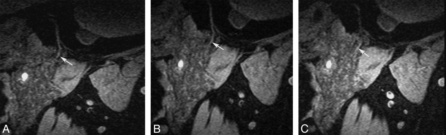
Different voxel sizes by the 3D-PSIF-DWI sequence with a surface coil. A, Voxel size of 0.4 mm. B, Voxel size of 0.5 mm; C, voxel size of 0.6 mm. All images can clearly display the main trunk of the intraparotid facial nerve and cervicofacial division. With the increased voxel size, the SNR will also increase at the expense of spatial resolution rate reduction.

SIR values of the facial nerve and parotid gland among different groups by the 3D-PSIF-DWI sequence with the surface coil. No significant difference was found between the SIR of intraparotid facial nerve and the SIR of parotid duct among these 3 groups.
Image Reformation and Interpretation of Reformatted Images
The obtained images were compared with images in Gray's Anatomy for Students (Fig 5). The main trunk and its branches were consistent with those in Gray's Anatomy for Students in 17 cases (17/21), while 4 cases were different from those in Gray's Anatomy for Students, which showed the temporofacial branch arising from the facial nerve trunk before entering the parotid gland.

Diagram illustrates terminal branches of intraparotid facial nerve. 1, temporofacial branch; 2, cervicofacial branch; 3, temporal branches; 4, zygomatic branches; 5, buccal branches; 6, marginal mandibular branches; 7, cervical branches.
The display rate of the temporofacial division and cervicofacial division was 100%, while the display rates of their secondary branches were 76.2% and 90.5%, respectively. The oblique sagittal and oblique coronal views were routinely used to depict the main trunks and cervicofacial division of intraparotid facial nerve. The temporofacial division was better displayed on an oblique axial reformatted image. The reformatted images presented more information than the source images.
Discussion
To depict the intraparotid course of the facial nerve accurately, the images should have high resolution and high contrast, which are capable of distinguishing nerve tissues from adjacent structures. Improved resolution on clinical 3T MR imaging units provides us with the opportunity to obtain high-resolution intraparotid facial nerve images and potentially meets a clinical need.
Current Research Status in Intraparotid Facial Nerve Imaging
With the head coil, 3D nerve imaging is based on gradient recalled-echo or spin-echo sequences, especially with T2WI or T2*WI, such as 3D constructive interference in steady state and 3D FIESTA.2,3 In these sequences, the high-intensity CSF contrasts sharply with the isointense nerve; however, for the facial nerve in its tympanic, mastoid, and parotid segments, there is no CSF surrounding the facial nerve. The intraparotid facial nerve displayed in 3D fast low-angle shot mainly relies on the high signal of fat tissue as a background, so it is difficult to distinguish the parotid duct from the intraparotid facial nerve, and one cannot detect small branches.4 In another report, 3D fast low-angle shot at 7T was used to image the facial nerve, but only a short part of the facial nerve near the skull base could be visualized.8 In addition, some scholars have used the 3D dual-echo steady-state water-excitation sequence to display the intraparotid facial nerve.9 Thus, although there are different MR imaging sequences that have been used to delineate the intraparotid nerve and parotid duct, significant limitations persist.
Principles and Advantages of the 3D-PSIF-DWI Sequence
The simultaneous visualization of the parotid duct and intraparotid facial nerve by using a 3D MR imaging sequence has been reported.6,10 The PSIF sequence is a steady-state free precession sequence with characteristics of a spin-echo sequence, first reported by Zhang et al11,12 for cranial nerve and lumbosacral plexus imaging. It has a dominant T2 contrast compared with other spoiled or refocused gradient-echo techniques, such as fast low-angle shot, gradient-recalled acquisition in the steady state, and free induction with steady-state precession. Given the anisotropic characteristics of the peripheral nerve, a diffusion gradient was imposed along the readout direction to obtain T2-weighted contrast images with diffusion-weighted characteristics. 3D-PSIF with a diffusion-weighted sequence achieves excellent nerve-muscle contrast and shows complete lack of signal from all moving structures, such as flowing blood, because the PSIF signal depends strongly on the steady-state condition.13 At the same time, uniform fat suppression by water-selective excitation at 3T was used. Hence, this sequence has the following characteristics: 1) It is nonsensitive to magnetic field inhomogeneity and is not prone to susceptibility artifacts; chemical shift artifacts are reduced by combining with water-excitation fat-suppression techniques. 2) This sequence is 3D Fourier-encoding with high spatial resolution, which can clearly display anatomic details and is available with MIP and MPR postprocessing. 3) These features allow the suppression of fat, vessels, and parotid gland parenchyma and permit the simultaneous visualization of the intraparotid facial nerve and parotid duct as structures with high signal.
In our study, we identified the intraparotid facial nerve as a linear structure of higher signal than the parotid gland and lower signal than the parotid duct. A significant difference was found in signal intensity between the intraparotid facial nerve and the parotid duct (t = 4.749; P = .000).
Surface Coil Combined with the 3D-PSIF-DWI Sequence in Displaying Parotid Gland Structures
To delineate the anatomy of cranial nerves accurately, images should have high resolution and high contrast and be capable of distinguishing nerve tissue from other solid structures. The surface coil used in our study is smaller than a traditional surface coil—it has only receiving functions and is placed close to the inspected object; it can provide higher resolution images compared with ordinary coils. With the decrease in coil size, the received noise is also reduced; this reduction ensures high SNR and high-resolution images. The parotid gland is suitable for surface coil imaging due to its small size and superficial location. Surface coils are used in other superficial organs requiring high resolution, such as temporomandibular joint, eye, skin, and muscle structure imaging.
In our study, the 3D-PSIF-DWI sequence by using a surface coil can obtain satisfactory image quality over varying voxel sizes. With the decrease of voxel size, the scanning time is gradually increased. If the scanning time is too long, then patient movement cannot be avoided. When the voxel size is increased, SNR will also increase at the expense of spatial-resolution-rate reduction. Considering image SNR and scanning time, we selected a voxel size of 0.6 × 0.6 × 0.6 mm in parotid imaging.
3D MR imaging has the ability to produce high-quality reformations. Some investigators emphasized the importance of selected angled imaging planes in demonstrating the major divisions of the intraparotid facial nerve.9,10 In our study, the main trunk and cervicofacial division of the intraparotid facial nerve were better displayed on the oblique sagittal and oblique coronal views, while the temporofacial division was better displayed on the oblique axial reformatted image. Compared with the secondary branches of cervicofacial division (identified in 90.5%), the secondary branches of the temporofacial division were more difficult to represent (identified in 76.2%) because they issued from the main division at a sharp angle and are not represented on the same planes.
Limitations
In this study, the intraparotid facial nerve and its divisions were analyzed on the basis of comparison with an anatomic atlas, not anatomic specimens. Most volunteers were young adults, so the 3D-PSIF-DWI protocol was not tested in different age groups. Individuals in different age groups have variable fat infiltration within the parotid gland that may influence imaging quality. Older subjects might have more fatty infiltration of the parotid gland, which might have good signal suppression of parotid parenchyma. Further study is necessary to assess the utility of 3D-PSIF-DWI in different age groups.
Conclusions
The 3D-PSIF-DWI sequence with a small-diameter surface coil can better delineate the intraparotid facial nerve and its divisions than when used with a head coil, providing better image contrast and resolution. The proposed protocol offers a clinically practical noninvasive imaging sequence for intraparotid facial nerve and parotid duct imaging at 3T.
Acknowledgments
We are grateful to our chief radiology technician, Zhongwei Zhang, MD, for 3D-PSIF-DWI technical support, and we thank Linda Zhang, MD, for helpful manuscript revision.
Footnotes
This work was supported by National Natural Science Foundation of China (No. 81201074).
Indicates open access to non-subscribers at www.ajnr.org
REFERENCES
- Received September 28, 2012.
- Accepted after revision November 24, 2012.
- © 2013 by American Journal of Neuroradiology


