
Abstract
BACKGROUND AND PURPOSE: Braided self-expandable stents and flow diverters of uniform construction may develop zones of heterogeneous porosity in vivo. Unwanted stenoses may also occur at the extremities of the device. We studied these phenomena in dedicated benchtop experiments.
MATERIALS AND METHODS: Five braided devices of decreasing porosity were studied. To simulate discrepancies in diameters between the landing zones of the parent vessel and the aneurysm neck area, device extremities were inserted into silicone tubes of various diameters (2–3 mm), leaving the midportion free to react to experimental manipulations, which included axial approximation of the tubes (0–7 mm), and curvature (0–135°), with or without axial compression (0–2 mm). The length of the landing zone was sequentially decreased to study terminal device stenosis.
RESULTS: All devices adopted a conformation characterized by 3 different zones: bilateral landing zones, a middle compaction zone, and 2 transition zones. It is possible, during deployment, to compact stents and FDs to decrease porosity, but a limiting factor was the transition zone, which remained relatively unchanged and of higher porosity than the expansion zone. Length of the transition zone increased when devices were constrained in smaller tubes. Heterogeneities in porosity with compaction and curvatures were predictable and followed simple geometric rules. Extremity stenoses occurred increasingly with decreasing length of the landing zone.
CONCLUSIONS: Braided self-expandable devices show predictable changes in porosity according to device size, vessel diameter, and curvature. Adequate landing zones are required to prevent terminal device stenosis.
ABBREVIATIONS:
- FD
- flow diverter
- FSS
- free segment of stent
- HPS
- high-porosity stent
- P
- porosity
- SF
- strut frequency
Some HPSs and most FDs used to treat intracranial aneurysms are constructed with multiple braided metal filaments to allow compression and loading into a microcatheter lumen. Once deployed into vascular structures of a larger diameter, these expand and shorten as they return toward their original size and conformation. We have previously shown in animal models that as these devices adapt to the constraints of local anatomy, the ensuing deformations can lead to substantial variations in device porosity between cases treated with the same device as well as wide variations in porosity along the different segments of the same device.1,2 Ideally, the aim of a flow-diversion treatment strategy is to form a tubular conduit of optimal porosity that will normalize linear flow, reconstruct the parent vessel, and effectively occlude the aneurysm while preserving arterial branches and perforators. Because the amount of “metallic coverage” of aneurysm and branch ostia may affect treatment safety and efficacy, it is desirable to accurately predict when and to what extent these deformations will occur and how these will influence device porosity.
We have previously tested both high-porosity braided self-expanding stents and flow diverters in wide-neck, bifurcation, and giant aneurysm models, and failures have occurred, particularly when devices were deployed in a curved configuration.1⇓–3 Device deformations and subsequent heterogeneity in device porosity were frequent and sometimes quite substantial.1⇓–3 When in vivo porosities of the portion of the devices bridging the aneurysm ostium were measured, it became clear that these were strongly influenced by the discrepancy in diameter between the parent artery and the portion of the device that was free to expand at the level of the aneurysm neck. This phenomenon could perhaps explain some failures of flow diversion and the lack of neointima formation at the neck of treated aneurysms, with persisting aneurysm filling despite FD treatment.2,3
In vitro studies that have hitherto been published have failed to uncover these variations because they studied stents and FDs in closed tubes.4 We here present the results of several simple experiments that permit a better understanding and more accurate prediction of the changes in structure of braided self-expanding stents and FDs as these adapt to the common types of geometric constraints encountered in treating aneurysms. This work can help inform the proper choice of stent and length of landing zone, and perhaps also illuminate some technical aspects of an intervention, in terms of the utility of the practice of intentional device compaction across the aneurysm neck.
Materials and Methods
Materials
The main characteristics of studied stents and FDs are summarized in Table and illustrated in Fig 1. These included 5 devices: 1 HPS, 1 low-porosity FD (FD48) similar to commercially available devices, and 3 prototype braided stent-in-stent endoluminal flow-diverting devices, composed of an outer HPS and an inner FD mesh of lower porosity and higher pore density, made with either 36, 48, or 64 wires, all gifts from MicroVention (Aliso Viejo, California). Experiments were performed with silicone tubes of various diameters (2, 2.5, and 3 mm), to simulate intracranial parent arteries and branches. Scaled microphotographs were taken for each experimental step with a stereo microscope and analyzed with image processing software (ImageJ; National Institutes of Health, Bethesda, Maryland).
Device characteristics
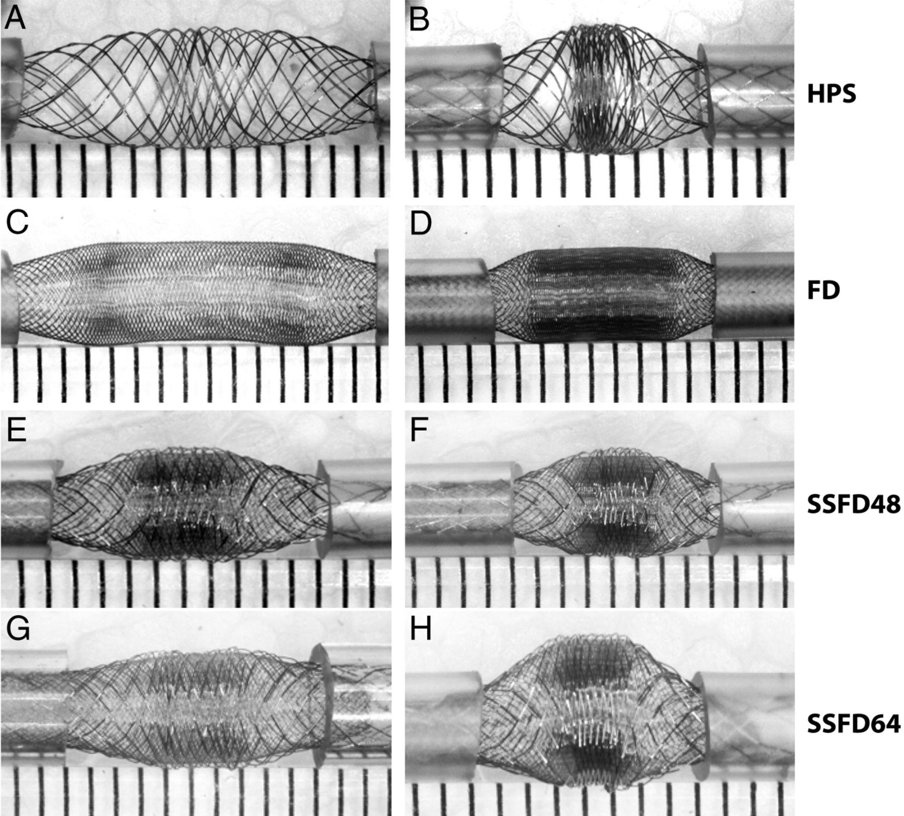
Devices. The first set of experiments is shown, in which various devices were used. Note the similar pattern shared by all braided devices, with a concentration of stent struts in the midportion of the device, compacted between relatively porous segments. The phenomenon, more marked with increasing compaction (as shown on the right side), leads to heterogeneities in porosity along the length of the same device.
Methods
In each experimental setup, the stent or FD was submitted to constraining conditions but also allowed to “react” to those conditions. The device extremities were 1) constrained within tubes of various diameters (simulating the parent artery or a branch of a bifurcation), and forced to follow geometries (curves of decreasing radii of curvature for example) or compacted by axial approximation of the tubes but 2) the device midsection was free to expand or adapt between constrained extremities (simulating the room made available at the level of a bifurcation and/or the neck of the aneurysm) (Fig 1). The pattern of strut distribution after each deformation was used to differentiate 3 different zones, which will be described. In each zone, parameters that were recorded included SF, defined as the number of struts per unit length, porosity (P), defined as the proportion of the surface area without metal coverage over total surface area, and pore density, the number of metal-enclosed pores per unit surface area. The effect of tube size was analyzed for each set of experiments. SF at different degrees of axial compression was determined by selecting a given stent segment and counting the number of struts per unit of length; and P was determined by measuring (1 − Total Metal Surface Area) × 100%. For a given device, there is a direct relationship between P, SF, and pore attenuation. P will be used as the variable for most reported results.
The experiments can be divided into 3 sets:
The first set was designed to test the impact of axial compression (0–7 mm) on strut distribution within the portion of the device free to react to such manipulations, the free segment of stent (or FSS). The experiments were repeated with extremities of the device inserted in tubes of 2, 2.5, and 3 mm in diameter. The hypothesis was that, because the surface of a cylinder can be estimated by the formula: 2πrl (where r and l are the radius and length of the cylinder), any decrease in the length available for metallic deployment, in the absence of a change in radius (changes do not occur in the midportion of the stent; see below), would automatically result in a proportional increase in SF or metallic attenuation and a decrease in porosity according to the formula: SF2/SF1 = l1/l2 = 1 − P2/1 − P1. This relationship was verified empirically.
The second set of experiments evaluated the effects of curvatures on porosity. Devices deployed into silicone tubes of various diameters at each extremity were bent to 0, 45, 90, and 135°. For each curvature, stents and FDs were also shortened bilaterally by 0–2 mm to measure the impact of axial compression combined with curvature on parameters of interest. The stent strut distribution was compared between the convex and the concave surfaces of the FSS and at the level of various stent and FD zones. The hypothesis was that as the device follows the curve, the length available for the distribution of metal struts would differ between the convex and concave side of the curvature, with P and SF varying according to the ratio of the arc of the convex surface (Cv) over the arc of the concave surface (Cc): SFv/SFc = Cv/Cc = 1 − Pc/1 − Pv. The strength of the correlations between dependent variables (eg, distance between tubes, arc ratios) and resulting porosities were estimated by using the Pearson correlation coefficient R2.
The final set of experiments was designed to assess the behavior of the terminal ends of the device within the various sizes of silicone tubes, to simulate landing zones. The length of the landing zone was sequentially decreased, and the diameter of the terminal end of the device was measured. Various devices (HPS, FDs, stent-in-stent endoluminal flow-diverting devices with 48 or 64 wires) were deployed into silicone tubes of 2-, 2.5-, and 3-mm diameters. Experiments were repeated in glass tubes of the same diameter. Overall, 370 experiments were performed.
Results
Zones
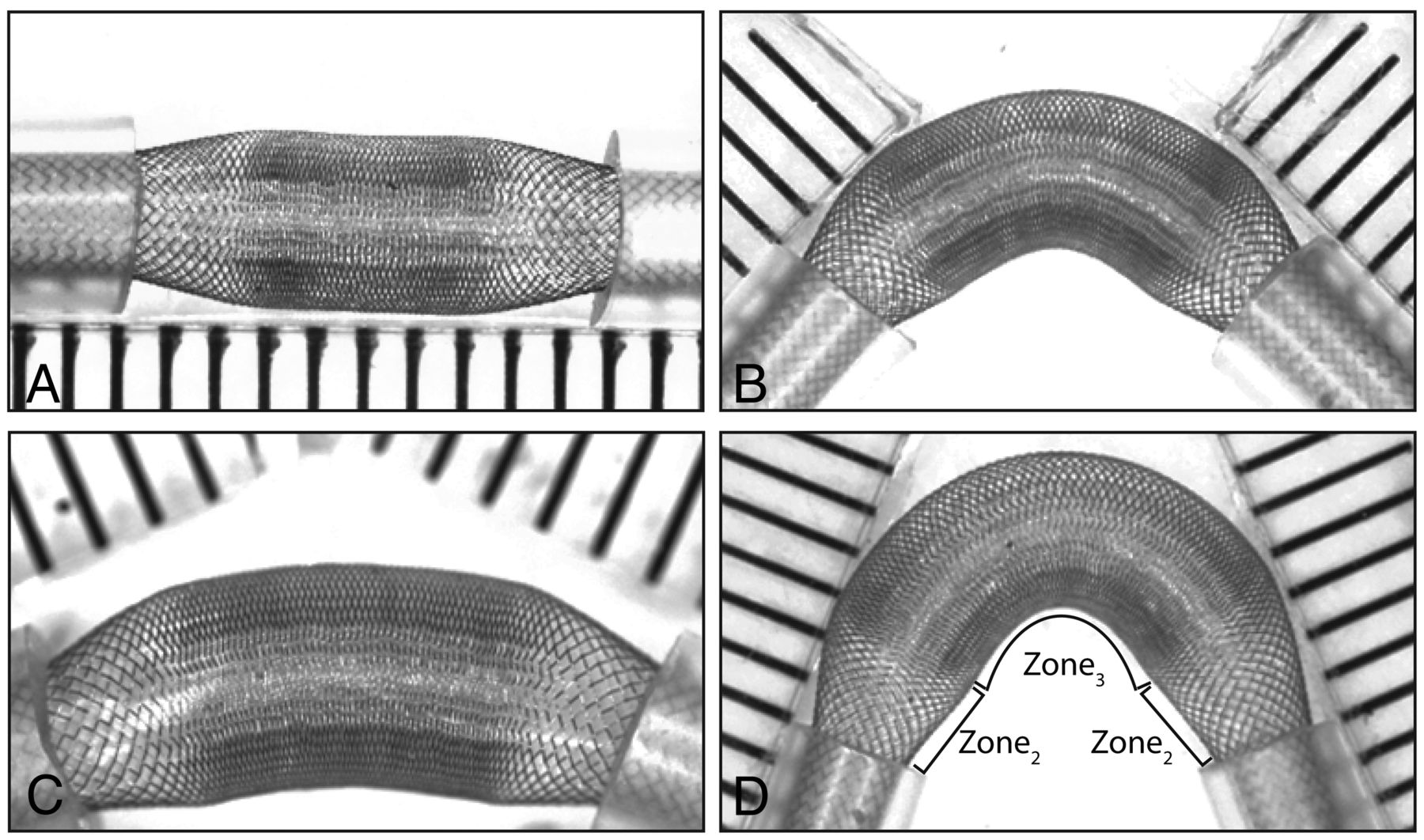
Placement of both ends of all devices into the tubes led to a redistribution of the struts according to 3 distinct zones, shown in Figs 1 and 2. The constrained or landing Zone1 is the portion still inside the silicone tube; the unconstrained segment of the stent or FD, the FSS, can be further divided into 2 transition Zone2, beginning immediately as the stent exits the tube, on both sides, and a middle expansion Zone3, where the device has been allowed to expand completely, found between each transition Zone2 (Fig 3, A–D). Both the inner and the outer stents of the stent-in-stent endoluminal flow-diverting devices displayed the same pattern (Fig 1, E–H).

Zones. The 3 characteristic zones are illustrated in a severely compacted HPS (A). Progressive approximation of the tubes (axial compression) leads to decreasing porosities of the compaction Zone3, but Zones1and2 remain relatively unchanged, as shown in B (HPS in 2-mm tubes). Axial compression leads directly to a shortening of Zone3, but the transition Zone2 length remains relatively unchanged (C). The same phenomenon was reproduced with the FD48 (compare B and D), with porosities reaching 0 with severe compaction.

Compaction and diameters. Effects of 2-mm (left column) and 4-mm compaction (right column) and of tube diameters (2–3.5 mm) on the compaction Zone3 and the transition Zone2 of the HPS are shown (A–H). Note that tubes of decreasing diameters lead to increased compaction of Zone3 because the transition Zone2 increases in length as tube diameter decreases. The relationship between the length of the transition Zone2 and the size of tubes is illustrated in I for both the HPS and the FD48.
Landing Zone1
Constraining the device in tubes of progressively smaller diameter led to a small but linear decrease in porosity within the landing Zone1 (for example, from 90% to 87 ± 2% for the HPS). Application of axial compression, bending, or combined axial compression with bending did not change the strut frequency or porosity of the device within this Zone1 (Fig 2B, -D).
Transition Zone2
The free segment of stent is composed of 2 transitions Zone2 and 1 compaction Zone3. The transition Zone2 exists because of the difference in diameters between landing Zone1 (constrained within the tube) and Zone3 (free to expand). The transition Zone2 is absent if the device has the same or smaller diameter than the tube (or parent vessel). With tubes of decreasing diameter, or with progressive relative oversizing of the device, the transition Zone2 becomes longer (Pearson R2 = 0.99) and an increasing proportion of the FSS is occupied by the more porous transition Zone2 (Fig 3). In all cases, the porosity follows a gradient, progressive and continuous along Zone2, between the maximum values found within the tube (Zone1) and the minimal values found at Zone3. Axial compression and progressive curving had minimal effect on the porosity of the transition Zone2 (Figs 2⇑–4).

Curvatures and FDs. Curvatures affect porosities of the convexity and concavity of FD48. The effects are limited to the compaction Zone3, the transition Zone2 being relatively spared.
Expansion Zone3
The expansion Zone3 is the only segment of the FSS that responds to compaction and angulation of the device. The 2 extremities of Zone3 consisted of 2 areas that appeared to be more dense in metallic coverage than the middle of Zone3 (Figs 1 and 3). For simplicity, and because this distinction disappeared with increasing compaction, these will not be considered as individual entities. In contrast to the transition Zone2, this portion of the stent underwent a significant decrease in porosity with approximation of the tubes. In keeping with our hypothesis, this follows a linear correlation with Pearson R2 values of 0.93 or greater for all devices. With axial compression of 0–7 mm, the HPS porosity went from 80% to 72% and, for FDs, from 53% to 0% (Fig 2, B–D).
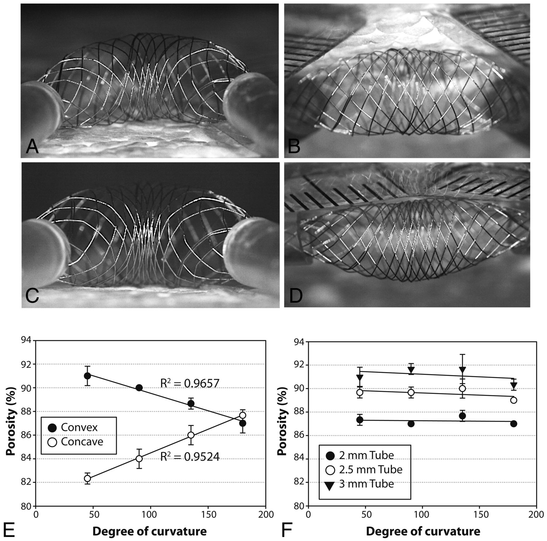
Bending the device from 0 to 135° increased porosity on the convex surface of the compaction Zone3, while decreasing porosity on the concave surface (Fig 5). The change in porosity was directly proportional to the arc ratios, as hypothesized, with Pearson R2 values of 0.95 for the HPS. Axial compression of the curved device, regardless of the degree of curvature, had the effect of “compacting” or increasing SF, thus decreasing the porosity of both the convex and the concave surfaces, but only within the compaction Zone3; the transition Zone2 and landing Zone1 remained unchanged (Figs 4 and 5).

Concavity at 45°(A, C) and convexity at 135°(B, D) of expansion Zone3 before (A, B), or after (C, D) the stent is compacted. Curvatures affect the porosity of the convexity and concavity sides of the compaction Zone3 (E), whereas the transition Zone2 remains virtually unchanged by comparison (F, showing the porosity of the transition Zone2 with different tubes and different curvatures).
Minimal Length of the Landing Zone1
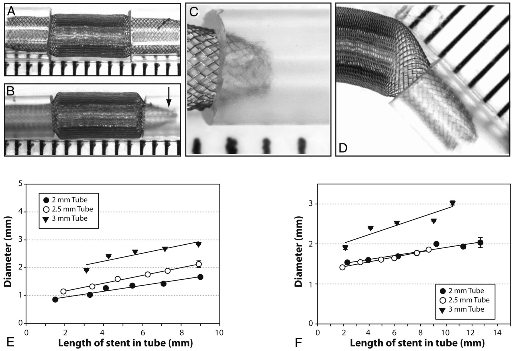
With all FD devices deployed into silicone tubes, some degree of stenosis at the terminal ends could be observed. No such phenomenon was noted with the HPS or when we deployed devices into glass tubes. The stenosis increased from a minimal (4%) to severe (60%) stenosis as the length of the landing Zone1 was progressively decreased, as shown in Fig 6. The stenosis-producing phenomenon became more pronounced with more marked mismatch between the diameter of the FDs and that of the constraining tubes. The stenosis at the ends of the device was more pronounced with devices of lesser nominal porosity. When a short landing zone was combined with a substantial angulation, the stenosis was asymmetrical (Fig 6).

Stenoses can occur at the level of device extremities (A–D); the stenosis is more severe when the length introduced inside the tube is insufficient (compare A and B), and eccentric when the device is curved (D). The relationship between stenoses and length of device introduced inside tubes is shown for FD48 (E) as well as for the 48-wire stent-in-stent endoluminal flow-diverting devices (F).
Discussion
The salient findings of this study are as follows:
Braided stents and FDs can exhibit major heterogeneities in porosity as these are subjected to various experimental conditions, including being simultaneously constrained into vessels of a smaller diameter than their nominal diameter but free to expand between the 2 constrained extremities.
The device adapts according to 3 characteristic zones.
It is possible to compact stents and FDs and to a certain extent decrease porosities in hope of increasing efficacy of the stenting or FD strategy, but this works only at the level of the compaction Zone3; a limiting factor is the transition Zone2, of relatively higher porosity, which remains relatively unchanged.
Changes in porosity due either to deployment techniques such as compaction or anatomic factors such as curvatures are predictable once it is recognized that changes are limited to the compaction Zone3; these predictable alterations follow relatively simple geometric rules.
Stenoses at the level of the stent extremities can occur if the landing zone is too short.
We have tested high porosity braided stents and flow diverters in wide-neck, bifurcation, and giant aneurysm models, and failures have occurred, particularly when the device was deployed in a curved configuration.1⇓–3 When in vivo porosities of the segments of devices bridging the aneurysm ostium were measured, it became clear that these were strongly influenced by discrepancies in diameters between the parent artery and the segment free to expand at the level of the aneurysm neck or bifurcation. Device deformations and subsequent heterogeneity in device porosity were frequent and sometimes severe.1⇓–3 The invariably increased porosity at the transition Zone2 may perhaps explain some failures of flow diversion, along with a lack of neointima formation across the neck of treated aneurysms and persistent filling after treatment.1,2,5
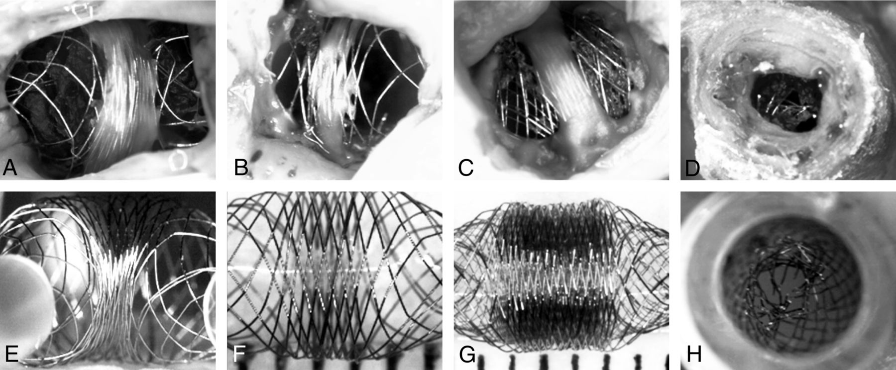
The benchtop experiments presented here were designed to model in vivo findings we encountered after experimentation in a canine aneurysm model, as shown in Fig 7. Many of our observations were most obvious when there was a significant discrepancy between stent size and vessel lumen. Previous in vitro studies have emphasized the importance of matching the size of the device with the diameter of the parent artery,4 and to this we are adding that device oversizing may also increase the length of the transition zone, a segment of device whose porosity is greater than the expansion zone. It is noteworthy that unlike the compaction zone, the porosity of the transition Zone2 cannot be decreased with technical maneuvers such as axial compression.

In vivo and in vitro observations. Photographs of 4 autopsy specimens of aneurysms treated with HPSs (A, B) or FDs (C, D) are compared with 4 photographs of benchtop studies designed to mimic in vivo findings (E–H). Note how neointima formation (A–C) tends to be limited to the less porous compaction Zone3, and how the transition Zone2, lacking neointima, may be responsible for failures. The in vivo stent stenosis (D) is reproduced inside a tube (H).
The problems with device deployment into curved configurations have previously been studied, with an emphasis on changes in flow patterns, the angle progressively converting shear-driven into inertia-driven flows.6,7 The increased porosities on the convexity of an acute curve may also decrease the efficacy of a FD strategy.2,4 This has recently been shown in computational fluid dynamics models.7 Although the bench experiments can show the changing porosity of the device, the reality of deploying flow diverters within a curve is more complex. Transmitting force around a corner to get the device to open can cause problems when treating patients with FDs. Prior understanding of patient-specific blood vessel and aneurysm anatomy, along with required degree of curvature of the deployed endovascular device, would be important elements to consider when attempting to prescribe an amount of metallic coverage over an aneurysm or important branch ostium. Industry partners should develop charts or graphs of resultant device porosities, at each device diameter, depending on parent vessel diameter, and approximate curvature, to facilitate the prescriptive process.
Because the problems we describe here have now been reproduced with all devices we have tested, these seem to be intrinsic to their braided self-expandable nature. Ways to circumvent or palliate the problems can be imagined: intra-aneurysmal coils may prevent some expansion of the device at the level of the neck, or telescoping stents or flow diverters of progressively smaller diameters may decrease the discrepancies and minimize the phenomenon. These techniques should first be attempted in preclinical studies, because they may potentially increase other types of complications, such as parent vessel thrombosis.
Device stenosis occurring at the terminal ends of a device has been documented in some animal models, particularly when the device undergoes substantial expansion into the aneurysm neck (where a more marked discrepancy exists between diameters at the aneurysm ostium and the parent artery), with short landing zones (Fig 6). The present study suggests that this phenomenon may be prevented by choosing a long enough device to leave adequately long landing zones on either side of the aneurysm neck. Device manufacturers could also provide data on anticipated degree of device stenosis at each length of landing zone.
Limitations
Many devices used for this study were prototypes, and results may not apply to clinically available FDs. Recently, the HPS has been approved in Europe and Canada (LVIS; MicroVention). The FD48 construction was modeled on the Pipeline device (ev3, Irvine, California). In vitro experiments were done in artificial environments, and although many phenomena have been documented in experimental animals, it is unclear whether and to what degree the same problems occur with currently approved intravascular devices in clinical applications. In vivo conditions may differ significantly from our experimental conditions, and any inference to human applications must be cautious.
Conclusions
Braided stents and FDs may exhibit heterogeneities in porosity that are to a certain extent predictable. Carefully matching device and parent vessel diameters and providing sufficient landing zones may prevent deformations that could affect the clinical results of stent placement and flow diversion in the treatment of complex aneurysms.
Footnotes
Disclosures: Jean Raymond—RELATED: Grant: FARQ/FRSQ, Comments: This work was partially supported by the Fondation de l'Association des Radiologistes du Québec (FARQ) in collaboration with Fonds de la Recherche en Santé du Québec (FRSQ) grant (to Dr. Jean Raymond). This work was also supported by a pilot project grant from the Society of Interventional Radiology (SIR) to Dr Tim Darsaut and by an imaging research bursary fellowship from Société Française de Radiologie to Dr Fabrice Bing; Other: Stents and FDs were gifts from MicroVention.
References
- Received March 5, 2012.
- Accepted after revision May 16, 2012.
- © 2013 by American Journal of Neuroradiology
In this issue


Jump to section
Related Articles
Cited By...
- Comprehensive Analysis of Post-Pipeline Endothelialization and Remodeling
- Braid stability after flow diverter treatment of intracranial aneurysms: a systematic review and meta-analysis
- Predictors of the Effects of Flow Diversion in Very Large and Giant Aneurysms
- Predictive score for complete occlusion of intracranial aneurysms treated by flow-diverter stents using machine learning
- A realistic way to investigate the design, and mechanical properties of flow diverter stents
- Comparison of Pipeline Embolization Device Sizing Based on Conventional 2D Measurements and Virtual Simulation Using the Sim&Size Software: An Agreement Study
- Ostium Ratio and Neck Ratio Could Predict the Outcome of Sidewall Intracranial Aneurysms Treated with Flow Diverters
- Toward Better Understanding of Flow Diversion in Bifurcation Aneurysms
- Flow-Diversion Effect of LEO Stents: Aneurysm Occlusion and Flow Remodeling of Covered Side Branches and Perforators
- Flow Diversion with Low-Profile Braided Stents for the Treatment of Very Small or Uncoilable Intracranial Aneurysms at or Distal to the Circle of Willis
- Compacting a Single Flow Diverter versus Overlapping Flow Diverters for Intracranial Aneurysms: A Computational Study
- Virtual-versus-Real Implantation of Flow Diverters: Clinical Potential and Influence of Vascular Geometry
- Compaction of flow diverters improves occlusion of experimental wide-necked aneurysms
- The Added Value of Volume-of-Interest C-Arm CT Imaging during Endovascular Treatment of Intracranial Aneurysms
- Pipeline endovascular device for the treatment of intracranial aneurysms at the level of the circle of Willis and beyond: multicenter experience
- Flow diverters: inter and intra-rater reliability of porosity and pore density measurements
- Preliminary experience with the Pipeline Flex Embolization Device: technical note
- Visual Outcomes with Flow-Diverter Stents Covering the Ophthalmic Artery for Treatment of Internal Carotid Artery Aneurysms
- The Success of Flow Diversion in Large and Giant Sidewall Aneurysms May Depend on the Size of the Defect in the Parent Artery
- Enhanced Aneurysmal Flow Diversion Using a Dynamic Push-Pull Technique: An Experimental and Modeling Study
- Building Multidevice Pipeline Constructs of Favorable Metal Coverage: A Practical Guide
- Variable Porosity of the Pipeline Embolization Device in Straight and Curved Vessels: A Guide for Optimal Deployment Strategy