
Abstract
BACKGROUND AND PURPOSE: The carotid siphon is a natural barrier to intracranial interventions. Our aim was to make a model of the human intracranial internal carotid artery (ICA) and to test the navigability of covered stents for intracranial applications.
MATERIALS AND METHODS: A digital tube was made on the basis of raw MR images of the human ICA. It was transferred into 10 physical models and then coated with silicone by using a 3D rapid prototyping (RP) machine. Ten dogs then underwent surgery. Their common carotid arteries (CCAs) were exposed, cut, and passed through 1 of the tubes. Finally, the vascular models were made by reanastomosis of their CCAs. Eight expended polytetrafluoroethylene (e-PTFE) covered stents (two 3.5 × 16 mm, two 3.5 × 13 mm, two 3.5 × 10 mm, and two 3.5 × 7 mm) were implanted 1 week later. Two dogs remained as controls. The performance of the device was evaluated by angiography and histopathologic examination.
RESULTS: Ten animal models were successfully constructed. There was no vascular spasm or thrombosis when assessed by angiography. Destruction of the tunica intima and media was found in the 3.5 × 16 mm stent group. Destruction of the endothelium was found in the 3.5 × 13 mm stent group, and only flattening of the endothelium was found in the 3.5 × 10 mm and 3.5 × 7 mm stent groups.
CONCLUSIONS: The experimental model was thought to simulate adequately the geometry of the human ICA and, thus, would be an effective tool for the research and testing of neurovascular devices. The length of the stent is 1 factor influencing the navigability in tortuous vessels.
Cerebrovascular diseases have increasingly been treated with intravascular approaches, but the geometry of the internal carotid artery (ICA) has made the delivery of such devices more difficult. A vascular model having the geometry of the human ICA and real blood flow would provide an effective tool for testing neurovascular devices. The reported models of the carotid siphon only roughly simulate the geometry and are different from the real human ICA.1,2
Rapid prototyping (RP) manufacturing technology has been applied in medicine since 1990.3 At present, RP technology has been widely used in neurosurgery, oral and maxillofacial surgery, orthopedics, and tissue engineering.4-6 Vascular application has already been reported.7-9 With the development of computer science, the axial images of cranial vessels from the human brain can be reconstructed and exported in a digital format. RP technology can change this digital format into a real model. A vascular model with 4 bends was made in this experiment in an effort to duplicate the geometry of the human ICA on the basis of MR angiography and RP technology. Covered stents of different lengths were tested and evaluated.
Materials and Methods
Construction of a Digital Model and Data Processing
A 68-year-old male patient underwent an MR imaging (Achieva, 3T; Philips Medical Systems, Best, the Netherlands). Sequence 3D time-of-flight MR angiography (3D-TOF-MRA) was chosen with the following parameters: FOV, 250 (anteroposterior [AP]) × 190 (right-to-left [RL] × 108 mm foot-to-head [FH]); sections, 180; thickness, 20 mm; voxel size, 0.342 (AP) × 0.7 (RL) × 0.6 mm (FH); coils, Head-8 (Philips Medical Systems); reconstruction voxel size, 0.244 mm; reconstruction matrix, 1024. The original axial MR images were stored and exported in standard DICOM format. As shown in Fig 1A, the left ICA of the patient is adequately simulated after 3D volume reconstruction (VR). The area of interest includes 4 successive siphon bends preceding the terminal bifurcation.

A, VR image of the MRA of the left ICA and its branches in the patient. B, The real tube is made of TangoPlus by the RP machine. It has the major bends of the carotid siphon. The thickness is 1.5 mm and the diameter is 5 mm. C, The tube is coated with silicone gel.
The axial images in DICOM format were imported by using Mimics software (Mimics 11; Materialise, Leuven, Belgium). After 3D reconstruction and editing, the 3D data of 1 intracranial ICA was obtained and transferred into stereolithography (STL) format. These 3D STL data were then read by using Pro-Engineer software (Pro-Engineer Wildfire V3.0; Parametric Technology, Needham, Mass). A tube was made whose axis was aligned to the axis of the STL image of the artery. The tube was defined with an inner diameter of 5 mm and a wall thickness of 1.5 mm. After this processing step, the 3D data of this tube were exported in STL format.
Construction of the Physical Model
The 3D RP printer (Eden350; Object Geometries, Rehovot, Israel) can manufacture the physical model of STL 3D data (Fig 1B). This portion of the process was completed by Wuxi Easyway Models Design and Manufacturing. The material (TangoPlus FullCure 930; Object Geometries) has certain desired elastic properties and is semitransparent white. Afterward, the supporting material (FullCure 705 support resin; Object Geometries) was separated from the fully-cured model by water jet.
The silicone rubber coating was produced by mixing 50 mL of component A and 50 mL of component B of Medical Silicone Gel (Silastic Biomedical grade ETR Q7–4780; Dow Corning, Auburn, Mich). A Contractor 5301 (Eppendorf, Hamburg, Germany) was used to remove the air bubbles inside the silicone rubber by vacuum pumping 3 times for 5 minutes each time. The silicone was then applied onto both the outer and inner surfaces of the model. The model with the silicone (Fig 1C) then needed to age for 1 week at room temperature before it was used.
Development of the Animal Model
The protocol for this experiment was approved by the animal research committee of our institution and was conducted in accordance with the guidelines of the International Council on Animal Care. All animals were maintained on a standard laboratory diet. Ten dogs (Animal Experiment Center, Shanghai, China) weighing 12–14 kg were used. The dogs fasted overnight before surgery, and the model surgery was performed with the dogs under general anesthesia using 5% (50 mg/mL) sodium thiopental at a dose of 30 mg/kg.
Under flowing water, a thread was passed through the tube model. The sterile field included the neck and the upper part of chest. An incision of approximately 10 cm was made in the middle of the anteroinferior neck. Approximately 10–12 cm of both CCA was exposed and freed from the musculature by using blunt separation. The distal portion of the left CCA and the proximal part of the right CCA were ligated and cut. The left CCA was threaded through the model with the thread. Two vascular clips were used 2–3 cm distal to the end of both CCAs. Stumps were cut, and the lumena of the CCAs were then flushed with heparinized saline. After the vascular adventitia was peeled, an end-to-end anastomosis of the 2 arteries was made by point sutures (Surgical suture needles with thread 8-0; Shanghai Pudong Jinhuan Medical Products, Shanghai, China). Hemostasis was obtained. The vascular clips were removed and the vessel refilled. Finally, the device was embedded, fixed in the left neck, and a layered wound closure was performed (Fig 2).

A−C, The surgical method and procedure. An end-to-end anastomosis (arrow, C) is made distal to and outside the tube. D, The artificially created artery is full, filling after removing the clips. The tube is semitransparent; thus, the CCA inside can be seen.
Low-molecular-weight heparin (2500 IU twice a day) was administered for 3 days after the procedure. Aspirin (50 mg daily) and ticlopidine (125 mg daily) were administered beginning on day 4. Antibiotics were used routinely to prevent infection. MR angiography was performed on the test subjects immediately following surgery. Carotid angiography was performed 1 week later.
Comparison of Models
Following surgery, each subject was scanned by using the same MR imaging system (Achieva, 3.0T), and we used the same 3D-TOF-MRA sequence with the following parameters: FOV, 140 (AP) × 140 (RL) × 108 mm (FH); sections, 180; thickness, 20 mm; voxel size, 0.542 (AP) × 0.7 (RL) × 0.6 mm (FH); reconstruction voxel size, 0.244 mm; reconstruction matrix, 1024; coils, SENSE-NV-16 (Philips Medical Systems). After reconstruction, the curved vasculature was clearly demonstrated. The axial images in DICOM format were then read by using Materialise Mimics software, processed, and exported into STL format. The 3D STL data of the intracranial ICA of the patient and the vascular model of the dog were opened in the Pro-Engineer software. Comparison and assessment of the morphology were made by integration of the digital images after moving and rotating them.
Stent Testing
Carotid angiography and stent testing were performed 1 week after surgery (Fig 3). The model was tested for only 1 week in this experiment. The details of stent construction were previously described and are not presented here.10 Eight e-PTFE-covered stents (two 3.5 × 16 mm, two 3.5 × 13 mm, two 3.5 × 10 mm, two 3.5 × 7 mm; Willis, MicroPort Medical, Shanghai, China) were implanted, 1 in each of 8 dogs. With roadmap guidance, the stent was navigated through the model 3 separate times by using 2 approaches and was deployed at the distal segment outside the model. The remaining 2 dogs were used as controls and underwent carotid angiography only. Vascular reactions such as spasm and thrombosis were evaluated.
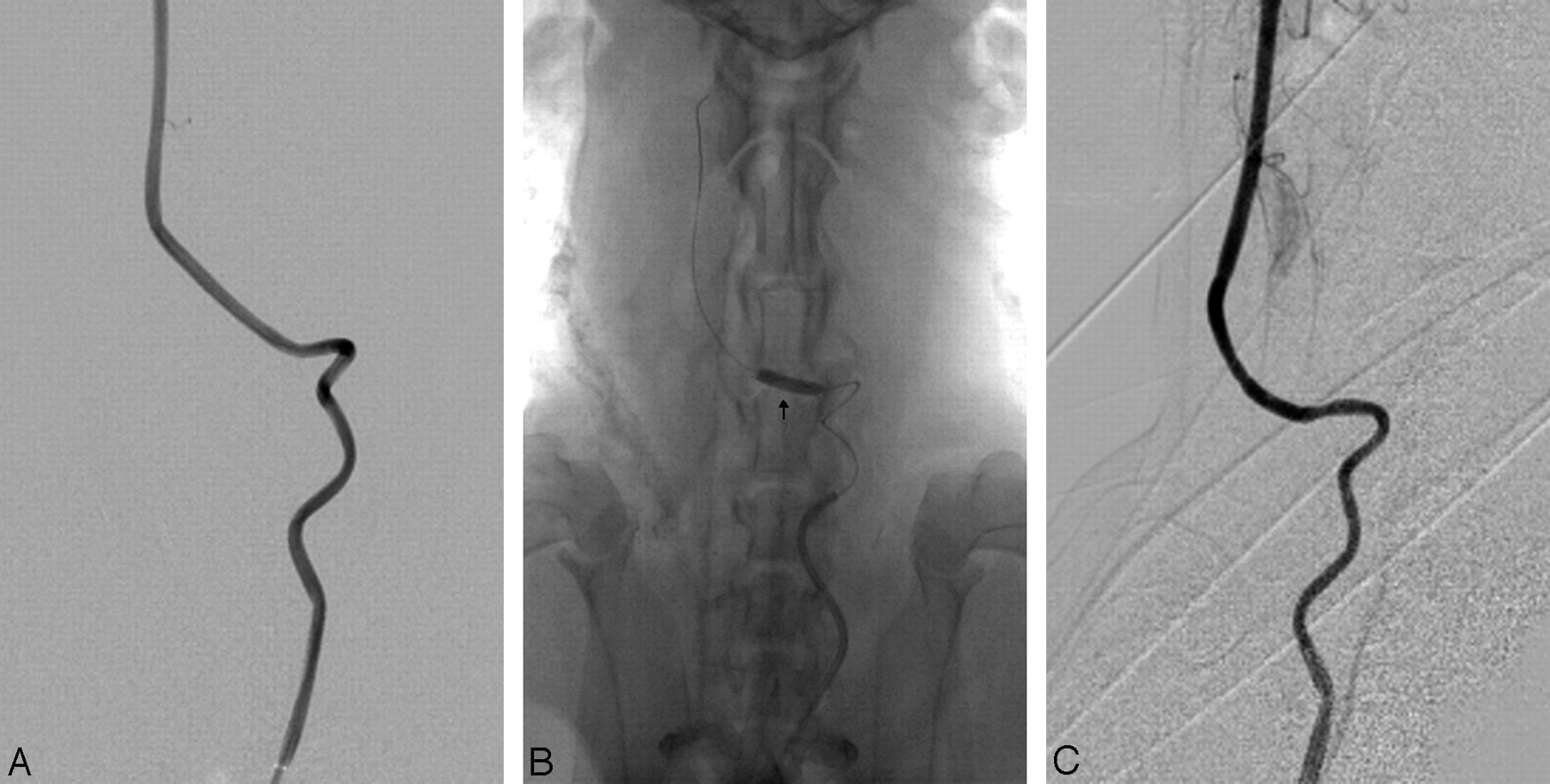
A, Angiogram before stent placement. The 4 bends of the artery are well demonstrated. B, Arrow shows the dilated balloon and the location of the stent. C, Angiogram after stent placement.
Evaluation
Both the navigability of the covered stent and the delivery system of the stent were determined by assessing its ability to pass through tortuous vessels, indicating flexibility. The system received the following navigability ratings: 1) successful A, no resistance with the covered stent reaching the targeted area smoothly; 2) successful B, no apparent resistance with the covered stent reaching the targeted area by adjusting the microguidewire; 3) difficult, resistance that could be overcome by adjusting both the microguidewire and the guiding catheter, thus allowing the covered stent to reach the targeted area; or 4) impossible, resistance such that the covered stent could not reach the targeted area even with the aid of the microguidewire and the guiding catheter.10
The dogs were euthanized under general anesthesia immediately following angiography and stent implantation. Surgical exploration of the vessel models was performed. After being fixed in 10% neutral buffered formalin for 24 hours, the vessel models were cut into 8 segments. Subsequently, the specimens were processed for both gross and microscopic examination.
Gross findings were performed to determine possible vessel injury during stent passthrough. The morphometric analysis of vascular injury was performed by an independent observer by using histology slides. Under microscopic examination, artery wall abnormalities were graded by using the following system1: 1) no injury, well-defined endothelial ridges present; 2) mild injury, flattening and destruction of endothelial ridges; 3) moderate injury, absence of endothelial ridges and areas of abrasion; and 4) severe injury, lacerations extending to the tunica media.
Results
Ten animal models were successfully produced. All dogs tolerated general anesthesia and surgical and endovascular procedures. The morphology of the vasculature in the dogs simulated the complex geometry of the human ICA. The 3D STL data of the intracranial ICA of the earlier patient were compared with the CCA of the dog by using Pro-Engineer software. The images demonstrated that the morphology of both arteries was highly similar (Fig 4). The artificial vascular bends were thought to simulate adequately the geometry of the human ICA. In addition, they appeared patent after 1 week.

Comparisons between CCA of the dog in the model (light red) and the human ICA (transparent dark red) before (A and B) and after (C and D) integration in different positions. The images of both arteries coincide well.
There was no vascular spasm or thrombosis revealed by angiography. After stent placement, destruction of tunica intima and tunica media was found in the 3.5 × 16 mm stent group. Destruction of the endothelium was found in the 3.5 × 13 mm stent group, and only flattening of the endothelium was found in the 3.5 × 10 mm and 3.5 × 7 mm groups (Table and Fig 5). Inflammation of the tunica adventitia was found in dog 3.

Microscopic findings after stent placement. A, Lacerations extending to the tunica media (arrow) (hematoxylin-eosin [HE], original magnification ×100). B, Destruction of endothelial ridges (arrow) (HE, original magnification ×200). C, Flattening of endothelial ridges (arrow) (HE, original magnification ×200).
Animals, devices, and angiographic and pathologic results
Discussion
The carotid siphon is a natural barrier to intracranial interventions. Forceful attempts to catheterize this vessel can result in thrombosis or spasm secondary to endothelial injury. Therefore, the neurovascular devices must undergo rigorous testing before being used in a clinical setting. The ideal model for testing neurovascular devices would have appropriate arterial geometry and real blood flow. Vessels in vitro are not suitable for testing because they lack the responsive features of viable vessels. Current models for the carotid siphon have not contained the true morphology of carotid bends. Some researchers have tried to construct a surgical bilateral siphon model in swine by using sutures.1 Others have used crooked devices in their siphon models.2 These devices contained only 1 bend; thus, they were still significantly different from the human ICA.
Our experimental design called for the left CCA of the dog to be threaded through a rigid tube containing 4 bends. The dogs were chosen not only for suitable length and diameter of their CCAs but also for their ability to tolerate the occlusion of blood flow. The tube used in the experiment had 4 bends, thus creating morphology quite similar to that of the human ICA. Some researchers suggest that the local hemodynamics in the ICA at physiologic flow rates are influenced by the succession of multiple bends. The geometry of the entire siphon must be properly modeled when studying aneurysm development.11 In addition, interventional difficulty increases when there is >1 bend. Four bends duplicate the physiologic interventional difficulties.
RP technology makes copying the morphology of the human ICA possible. The digital tube is based on the raw image on 3D-TOF-MRA, in which vessels have adequate contrast. Compared with CT angiography, MR angiography uses no contrast medium, and bony structures do not interfere with the images. However, the material that can be used in an RP printer is limited. TangoPlus is flexible, and it can be covered with silicone gel, which has good biocompatibility and stiffness after solidification. Tubes covered with this material can simulate the bony track through which the human ICA enters the bottom of skull. In this experiment, only 1 anastomosis of the 2 carotid arteries was used. The average time for completing the surgery was about 2 hours. Heparin and oral anticoagulants were used after surgery to keep the artery patent.
Pictures of the model and the human ICA can be integrated by using Pro-Engineer software. This integration allows the comparison to be more reliable.
Inflammation of the adventitia was found in dog 3. We think it was iatrogenic. Other reasons may include foreign body reaction and vascular injury. Because the material silicone has good biocompatibility and not all the vessels were infected, inflammation probably was not foreign body reaction. Vascular injury could not be the reason for the inflammation because there is little time between the test of the stent and the fixation of vessel specimens.
The carotid siphon model can test only the navigability of the intravascular devices. Usually low flexibility and oversize are the main causes for vessel injury after deployment. In the experiment, the tested stents were the same except for the length. Therefore, the length may be one of the factors influencing the navigability, especially in tortuous vessel.
Areas of this model can be improved in the future. The camber of the bends in the human carotid artery varies between individuals. The raw images in this experiment were from only 1 person. So, the geometry of this model cannot truly represent the full scope of variations in humans. When deploying the animal model, we still pulled the carotid artery of the dog while it went through the tube. The CCA can be thinner under the tension, and the segment of CCA inside the model would then run along the convex surface of the tube lumen. The curvature becomes smaller under this circumstance. In addition, the CCA can be pressed or angled at the 2 ends of the tube. Stenosis may occur under pressure. Moreover, stenosis of the anastomosis may occur during surgery and in the next week before angiography. Exposing a sufficient length of the CCA of the dog and very careful surgery could reduce or even obviate these defects.
Testing of the covered stent was preliminary and was studied to assess how useful the model could be, rather than for formal testing of the device itself. Further testing in more difficult configurations and comparisons with other stents would be necessary before reaching conclusions on this particular device.
Conclusions
This experiment provides a method to make a carotid siphon model in dogs on the basis of MR images from a randomly selected person. The experimental model was thought to adequately simulate the geometry of the human ICA and provide an effective tool to research and test neurovascular devices. The length of the stent is 1 factor influencing the navigability, especially in tortuous vessels.
Acknowledgments
We thank engineers Liang Wang and Chun-Hua Fan and the staff of the Experimental Animal Center for their invaluable assistance.
Footnotes
This work was supported by a grant from the National Natural Science Foundation of China, 30570540, to Ming-Hua Li.
References
- Received October 5, 2008.
- Accepted after revision December 1, 2008.
- Copyright © American Society of Neuroradiology


