
Abstract
Summary: We herein present our preliminary experience with functional MR imaging of the direct electrical stimulation of the cochlear nerve using an MR imaging–compatible electrode placed in the external auditory meatus of five patients with binaural sensorineural hearing loss. The stimulator was placed outside the imager's bore, and the electrode produced virtually no susceptibility artifacts. In three of five patients, it was possible to activate the superior temporal gyrus during functional MR imaging. No side effects were observed.
To predict the outcome of a cochlear implant for a patient with severe hearing loss, the clinician needs a reliable and objective method to assess the intactness of the cochlear nerve. The promontory test is one of the mainstays of the presurgical diagnostic workup of cochlear implant candidates. The test is conducted by electrical stimulation of the cochlear promontory after transtympanic insertion of a needle electrode with the patient under local anesthesia. The classical test is slightly invasive and subjective and may provide inconsistent results. A noninvasive and objective method is therefore desirable. A noninvasive objective method was developed using an auditory canal electrode (1). Previous experience with functional MR imaging as an objective tool with which to evaluate the promontory test has been encouraging, although the method is still slightly invasive and the results are severely degraded by susceptibility artifacts caused by the nerve stimulator (2). We took a different approach by placing the stimulator device outside the imager's bore and introduced a stimulating ball electrode in the external auditory meatus.
Technique
We used a modified MED-EL Electro Audiometer (MED-EL Corporation, Innsbruck, Austria) for electrical stimulation during MR imaging. This device is commonly used for the preoperative testing of cochlear implant candidates. It consists of a control and display box (transmitter) and a two-channel receiver-stimulator (left and right ear) to generate the stimulation current. The stimulation electrode (silver ball) is placed in the external auditory meatus near the eardrum, and the reference electrode can be placed either on the skin of the forehead or on the skin of the patient's neck. The control box permitted the selection of all stimulation parameters (63 Hz−2 kHz, 1.6−1613 μA) and triggered the stimulation (single 500-millisecond or continuous 5-Hz stimulation bursts, see Fig 1B-C). Data were transferred between the control box and the receiver-stimulator by infrared transmission.

Experimental setup and the different stimulation schemes used for the electrical stimulation of the auditory nerve during functional MR imaging. Stim. Sig., stimulation signal (stimulation information is transmitted from the control box of the Electro Audiometer, and the signal is generated in the receiver-stimulator); Rph, photo resistor impedance; Rdr, dark resistance of photo resistor; Pat. Sig., stimulation signal transmitted to patient; MR-Trig., MR-trigger signal; Im. Ac., image acquisition.
A, The entire stimulation setup is located within the shielded room. The electrode leads are disconnected by means of two photo resistors. The light for switching the photo resistors is transmitted via two optical fibers. The Electro Audiometer synchronizes the stimulator-receiver (receiver 2) and light source (receiver 1) by infrared transmission. Furthermore, the light source synchronizes the MR imager with the stimulation setup by applying an MR trigger signal to the imager after the photo resistors have disconnected the electrodes. State A (no stimulation) and state B (stimulation) are realized by a “beam shutter.”
B, Schematic diagram depicts synchronization between the current bursts used for electrical stimulation and image acquisition. The remaining time for safe imaging is 0.35 seconds for mode 1.
C, Schematic diagram depicts synchronization between the current bursts used for electrical stimulation and image acquisition. The remaining time for safe imaging is 0.7 seconds formode 2.
This Electro Audiometer was tested for MR compatibility at 1.5 T (Magnetom VISION, Siemens Medical Systems, Erlangen, Germany) by performing a performance test, an evaluation of artifacts, an in vitro and in vivo evaluation of temperature increase, and an evaluation of stimulation signal changes. Temperature was measured using a calibrated fluoroptic thermometer (model 710; Luxtron, Mountain View, CA) (3). In addition to the sequences intended for use in our functional MR imaging study, worst-case sequences (eg, repeated turbo spin-echo and half-Fourier rapid acquisition with relaxation enhancement sequences with a resulting specific absorption rate (SAR) corresponding to that of the first level operating mode) (4) were also applied. For the performance test and for the evaluation of stimulation signal changes, the output signal of the stimulator was monitored by an electro-optical transducer (5). To maximize RF-induced signals, sequences containing pulses with high RF peak amplitudes, such as 180° pulses in spin-echo sequences and pulse trains of very short 180° pulses in turbo spin-echo sequences, were applied. Concerning gradient-induced voltages, we used spin-echo and echo-planar imaging sequences, for which the field of view, section thickness, and section-selection direction were selected to produce high voltages.
These experiments indicated that safe functional MR imaging should be possible by modifying the described Electro Audiometer as follows. To avoid artifacts, the reference electrode has to be replaced by a carbon reference electrode. To protect the stimulator from the main magnetic field, it must be positioned outside the imager's bore at the end of the patient table. This means the electrode leads must be extended by4 meters. To prevent the stimulator from excessive RF-induced signals, a low pass filter (cut-off frequency, 21 kHz) must be used at the stimulator output. Electrostimulation and MR imaging sequences must not be performed simultaneously. To avoid eddy currents, the electrode leads must be disconnected while the sequence is applied. The disconnection of the electrodes and nonsimultaneous stimulation and image acquisition have to be taken very seriously because the ball electrode heats up (6.4° C), even with common spin-echo sequences. Only the sequences listed in our protocol should be applied; no sequences with a higher SAR strain should be used.
To avoid eddy currents, the electrode leads should be disconnected as close to their patient contacts as possible. To avoid any interference with the fields generated by the MR imager, two photo resistors were used to disconnect the electrodes. The light for switching the photo resistors is transmitted via two optical fibers. The Electro Audiometer synchronizes the stimulator-receiver and light source by infrared transmission. Furthermore, the light source synchronizes the MR imager with the stimulation setup by sending a trigger signal to the MR imager after the photo resistors have disconnected the electrodes. The rise and fall times of dark resistance are taken into account by delaying the trigger pulse until the maximum value for dark resistance is reached and by controlling measurement time (maximum, 0.35 second [mode 1] and 0.7 second [mode 2]). State A (no stimulation) and state B (stimulation) can be realized by a beam shutter (eg, hand), connecting or disconnecting infrared transmission and therefore triggering or stopping the stimulation process. The entire stimulation setup is located within the shielded room, which is important to avoid RF-induced artifacts (Fig 1).
After flushing the external auditory meatus of the patient with physiologic saline, the stimulating electrode was placed in the external auditory meatus and fixed with earplugs. The reference electrode was placed on the forehead by using MR imaging–compatible carbon ECG electrodes. The individual stimulation thresholds were ascertained before moving the patient into the imager. All patients experienced severe binaural sensorineural hearing loss and were cochlear implant candidates. During stimulation, they reported a hearing sensation of intermediate loudness, with the stimulus well below electrical discomfort. Stimulation consisted of 125 to 1000 Hz sine tone bursts at a pulse rate of 1 Hz (stimulation mode 1) or 5 Hz (stimulation mode 2), respectively. The stimulating current ranged from 150 to 650 μA.
We used a multi-section gradient-echo echo-planar imaging sequence (9600/46 [TR/TE]; flip angle, α = 90°; number of sections, four; section thickness, 5 mm; intersection gap, 2.5 mm; field of view, 250 mm; matrix, 64 × 64; number of acquisitions, 1; phase encoding, left-right). The whole sequence was repeated every 3 seconds, according to the stimulation protocol. One hundred twenty measurements were recorded with the resting and stimulating condition alternating after 10 measurements. The sections were oriented in the transverse plane, with the most cranial section at the level of the superior temporal gyrus. Image analysis was performed using the AFNI software package (R. Cox, Medical Center of Wisconsin) using a modified smoothed boxcar reference function for cross-correlation analysis and a threshold of .22 < r < 0.36 corresponding to a P value of <05. A cluster size of 500 to 600 μL (5 voxels) seemed sufficient to differentiate activation from scattered background noise. Measurements one through three of every time series were discarded to account for nonequilibrium effects. We used section-by-section motion correction. This correction was performed within AFNI with in-plane translation and rotation (three-parameter rigid body transformation). The results of the functional studies were superimposed onto anatomic gradient-echo images. In three of five patients, we observed an activation of the superior temporal gyrus, which was unilateral in two patients (contralateral to stimulation) and bilateral in one (predominantly contralateral to stimulation) (Fig 2). In two patients, no activation could be visualized because of severe motion artifacts in one case and problems with positioning of the stimulating electrode in the other. The clinical histories of these two patients were not different from those of patients in whom functional MR imaging was successful. A repeated examination was not performed. Available data being very preliminary, we did not observe any tonotopic organization nor was there any visible or measurable effect of stimulus presentation rate or intensity on activation.
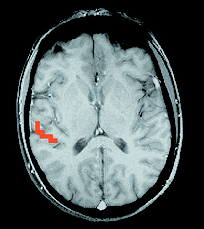
Activation of the right superior temporal gyrus after monaural left-sided stimulation.
Discussion
Acoustic stimulation of the primary auditory cortex and the associated areas has been reported in the functional MR imaging literature (6). Functional MR imaging used to study the auditory cortex is hampered by the loud noise inherent in echo-planar imaging sequences, which is superimposed onto the acoustic stimuli. This problem, however, does not apply to patients with severe sensorineural hearing loss. Previous functional MR imaging studies of deaf patients have shown the feasibility of functional MR imaging to study the direct electrical stimulation of the cochlear nerve with subsequent activation of the auditory cortex (2, 7). The techniques presented, however, were slightly invasive in that they required the insertion of the stimulation electrode either close to the round window membrane or at the cochlear promontory, in both cases necessitating the perforation of the tympanic membrane and the use of local anesthesia. Apart from being noninvasive, the novel method presented in this article is not limited by susceptibility artifacts. The potential clinical applications include the presurgical diagnostic workup of cochlear implant candidates (especially after prelinguistic auditory deprivation) in whom the functionality of the auditory pathways can be documented in an objective way. In addition to this, differentiation of central from peripheral and organic from functional hearing loss could be of clinical use.
Footnotes
↵1 Address reprint requests to Erich Hofmann, MD, Department of Neuroradiology, University of Würzburg, Josef-Schneider-Str. 11, D-97080 Würzburg, Germany.
- Received January 21, 1999.
- Copyright © American Society of Neuroradiology
In this issue


Jump to section
Related Articles
Cited By...
- No citing articles found.