
Abstract
BACKGROUND AND PURPOSE: Future aneurysmal behaviors or treatment outcomes of cerebral aneurysms may be related to the hemodynamics around the inflow zone. Here we investigated the influence of parent artery curvature on the inflow zone location of unruptured sidewall internal carotid artery aneurysms.
MATERIALS AND METHODS: In 32 aneurysms, the inflow zone location was decided by 4D flow MR imaging, and the radius of the parent artery curvature was measured in 2D on an en face image of the section plane corresponding to the aneurysm orifice.
RESULTS: The inflow zone was on the distal neck in 10 (group 1, 31.3%), on the lateral side in 19 (group 2, 59.4%), and on the proximal neck in 3 (group 3, 9.4%) aneurysms. The radius in group 1 was significantly larger than that in group 2 (8.3 mm [4.5 mm] versus 4.5 mm [1.9 mm]; median [interquartile range]; P < .0001). All 7 aneurysms with a radius of >8.0 mm were in group 1. All 18 aneurysms with a radius of <6.0 mm were in group 2 or 3. In two group 3 aneurysms, the inflow zone was located in a part of the neck extending beyond the central axis of the parent artery.
CONCLUSIONS: The inflow zone locations of sidewall aneurysms can be influenced by the parent artery curvature evaluated in 2D on an en face image of the section plane corresponding to the aneurysm orifice.
ABBREVIATION:
- IQR
- interquartile range
The hemodynamics around the inflow zone of cerebral aneurysms may be a principal cause of growth,1⇓⇓–4 bleb formation resulting in rupture,1,2,5⇓⇓–8 and regrowth following clipping surgery or endovascular coiling.9⇓⇓⇓–13 These sequelae are possibly related to the increased wall shear stress on the aneurysmal wall surrounding the inflow zone.2⇓⇓⇓–6,14 Therefore, both identification of the exact location of the inflow zone and evaluation of the hemodynamics around this area may contribute to predicting future aneurysmal behaviors or obtaining good treatment outcomes.15 Previous studies have estimated that neck width and geometric relationship between an aneurysm and the parent artery are dominant factors in the determination of the inflow zone location.1,14,16⇓⇓–19
4D flow MR imaging based on time-resolved 3D cine phase-contrast MR imaging techniques was recently used to evaluate the hemodynamics of cerebral aneurysms20⇓⇓⇓–24 and to identify the inflow zone of cerebral aneurysms.15 However, no previous studies have examined the correlation between the distribution of the inflow zone on the section plane corresponding to the aneurysm orifice and aneurysm morphology or the parent artery curvature in patient-specific imaging analysis, to our knowledge. Here we investigated the influence of morphologic factors or the parent artery curvature on the inflow zone location identified by using 4D flow MR imaging in unruptured sidewall ICA aneurysms.
Materials and Methods
Materials
This study was approved by the ethics committee of Mattoh-Ishikawa Central Hospital, and written informed consent was obtained from all patients. Both conventional 3D TOF MRA and 4D flow MR imaging were performed for 41 sidewall unruptured saccular ICA aneurysms. The following 9 aneurysms were excluded from this study: 8 aneurysms that exhibited unstable and irregular streamline patterns irrelevant to the vascular shape on 4D flow MR images, possibly due to motion artifacts or limitations of spatial resolution; and 1 aneurysm with a complicated neck configuration for which the section plane corresponding to the aneurysm orifice could not be determined. Accordingly, this study included 32 aneurysms (31 patients): Three were located on the cavernous segment; 3, on the paraclinoid segment; 16, on the medial C2 segment; and 10, on the bifurcation of the ICA and the posterior communicating artery. The maximum mean diameters of the aneurysms and the neck were 5.1 ± 1.7 mm (range, 2.6–10.7 mm) and 4.4 ± 1.3 mm (range, 2.1–7.8 mm), respectively.
MR Imaging
MR imaging was performed by a 1.5T MR imaging scanner (Magnetom Avanto; Siemens, Erlangen, Germany) with an 8-channel head array coil. The imaging parameters for 3D TOF MRA were as follows: TR/TE/NEX, 35/7.15 ms/average 1; flip angle, 22°; FOV, 150 × 123 mm; z-coverage, 45.6 mm; thickness, 0.6-mm; 3 slabs; 30 sections/slab; slab interval, −4.2 mm; matrix, 256 × 168 (512 × 336 with zero-filling interpolation processing); voxel size, 0.59 × 0.73 × 0.6 mm (0.295 × 0.365 × 0.6 mm with zero-filling); band width, 87 Hz/pixel; imaging time, 4 minutes 53 seconds; transaxial direction. For conventional 3D TOF MRA, vascular structures were constructed by using a volume-rendering method. The imaging parameters for 4D flow MR imaging were as follows: TR/TE/NEX, 33.05/5.63 ms/average 1; flip angle, 22°; FOV, 200 × 200 mm; 0.8-mm thickness; 1 slab; 24–26 sections/slab; z-coverage, 19.2 mm; matrix, 192 × 192; no interpolation processing; voxel size, 1.04 × 1.04 × 0.8 mm; velocity encoding, 80 cm/s; band width, 434 Hz/pixel; parallel imaging with reduction factor, 2; imaging time, 2–30 minutes depending on each patient's heart rate; transaxial direction; retrospective gating with an electrocardiogram; 20 phases.
We used a commercially available software (Flova II, Version 2.9.5; R'tech, Hamamatsu, Japan) to visualize the vascular geometry and spatially registered blood flow. The vascular structures were segmented by using the region-growing method,25 and vascular shapes were created by using the “marching cubes” method.26 The 3D datasets were converted to pixel datasets at a spatial resolution of 0.5 × 0.5 × 0.5 mm. The inflow zone was defined as the orifice area where components vertical to the section plane of the inflow vectors exceeding 60% of the maximum inflow velocity at peak systole were depicted on a 4D flow MR image. Using a function of the software, we selected this 60% range to avoid both an opaque depiction on the higher range and an exceeding expansion of the inflow zone area on the lower range, because they make it difficult to classify the inflow zone location in each case. Three of the authors (K.F., M.N., and F.U.) who have >15 years' experience in evaluating cerebral aneurysms on 3D TOF MRA images determined the window width and level of all the datasets and selected the section plane of the aneurysm orifice by consensus.
Using a function of a widely used software package (Keynote '09, Version 5.3; Apple, Cupertino, California), we drew a circle in 2D fitting the central axis of the parent artery segment that was developing the aneurysm on an en face image of the section plane corresponding to the orifice (Fig 1C). On the image, the circle to fit the midpoints of the parent artery width at both the proximal and distal ends of the aneurysm neck was selected. The radius of the curvature was measured on the image by comparison of the radius length of the circle with the length between 2 arbitrary points of which the actual length had been measured beforehand by using a function of Flova II. The radius of the curvature in this study is defined as the radius of the circle. Drawing the circle and measuring the radius were also performed on the basis of the consensus of 3 of the authors (K.F., M.N., and F.U.).
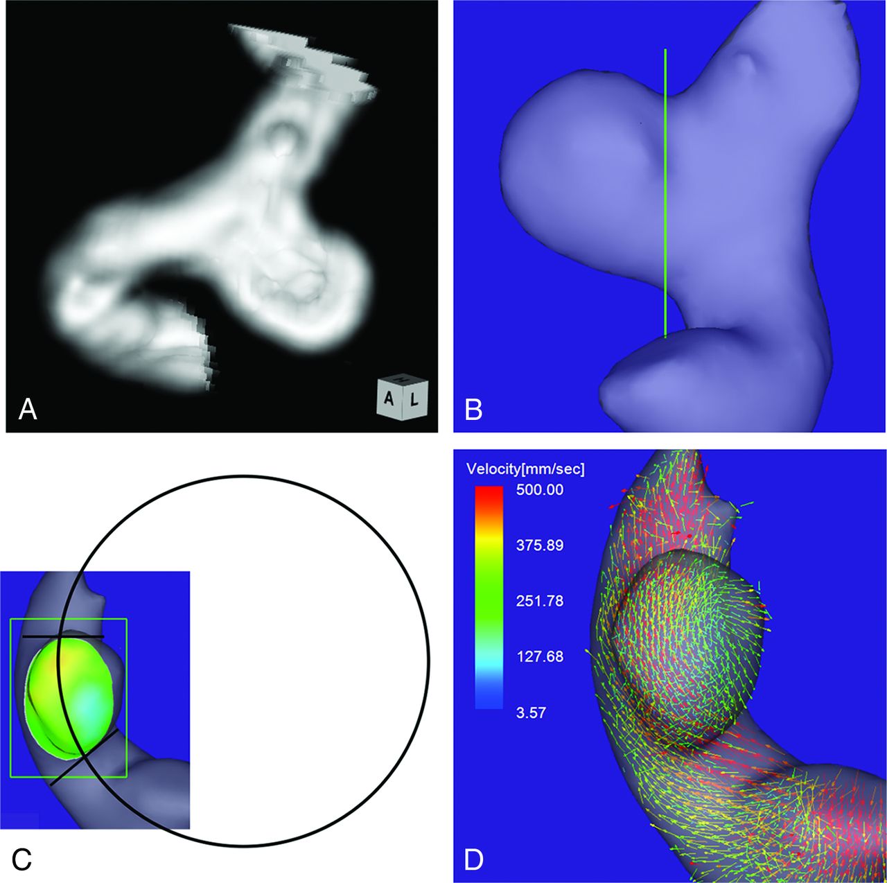
Case 1. A 64-year-old woman had an unruptured aneurysm at the medial C2 segment of the right ICA. A, 3D TOF MRA image. B, Image shows the section plane corresponding to the aneurysm orifice. C, En face image of the section plane. A 4D flow MR image demonstrates the inflow zone (orange) located on the distal neck and a circle in 2D fitting the central axis of the arterial part developing the aneurysm. The radius is 7.1 mm. D, A 4D flow MR image demonstrates a velocity vector map at peak systole.
Data Analysis
According to the positional relationship to the central axis of the parent artery, we classified the locations of the inflow zones of cerebral aneurysms into the following 3 locations: distal neck, lateral side of the neck, and proximal neck. We investigated the correlation of the radius to the inflow zone location. We also compared the inflow zone location with respect to morphologic parameters, including the maximum diameters of the aneurysm and its neck, maximum perpendicular height, maximum height, aspect ratio, and aneurysm size ratio.27⇓–29 These parameters were measured on conventional 3D TOF MRA.
Moreover, to clarify the correlation between neck size and inflow zone location, we measured the maximum orifice ratio obtained by the maximum neck diameter divided by the parent artery diameter and the width orifice ratio obtained by the maximum neck width divided by the parent artery diameter. The maximum neck width was measured on the direction perpendicular to the axis of the parent artery. Each numeric value of the various parameters was determined as the mean of the nearest 2 values independently estimated by the 3 readers.
Statistical analysis was performed by using the Mann-Whitney U test for continuous variables. P values < .05 were significant.
Results
Of 32 sidewall aneurysms, 4D flow MR imaging revealed that the inflow zone location was the distal neck in 10 (group 1, 31.3%), the lateral side of the neck in 19 (group 2, 59.4%), and the proximal neck in 3 (group 3, 9.4%). Between groups 1 and 2 and between group 1 and the other 2 groups, there was no significant difference with respect to morphologic parameters, including the maximum and width orifice ratios (Table). Figure 2 shows the distribution of the radius in the aneurysms by group. The radius was 8.3 mm (median; IQR, 4.5 mm), 4.5 mm (median; IQR, 1.9 mm), and 5.0 mm (median; IQR, 0.3 mm) in groups 1–3, respectively. The radius in group 1 was significantly larger than that in group 2 (P < .0001) and that in groups 2 and 3 (8.3 mm [median; IQR, 4.5 mm] versus 5.0 mm [median; IQR, 1.4 mm], P < .0001).
Aneurysm parameters: correlations between groups 1 and 2 and between group 1 and the other 2 groupsa

The distribution of the radius of the parent artery curvature measured in 2D on an en face image of the section plane corresponding to the orifice in group 1, 2, and 3 aneurysms. Group 1, 2, and 3 aneurysms have inflow zone locations on the distal neck, lateral side of the neck, and proximal neck, respectively. The radius in group 1 is significantly larger than that in group 2 (asterisk 1: 8.3 mm, median; interquartile range, 4.5 mm; versus 4.5 mm, median; IQR, 1.9 mm; P < .0001) or those in groups 2 and 3 (asterisk 2: 8.3 mm, median; IQR, 4.5 mm; versus 5.0 mm, median; IQR, 1.4 mm; P < .0001).
All 7 aneurysms with a radius of >8.0 mm were group 1 aneurysms. On the other hand, all 18 aneurysms with a radius of <6.0 mm were in group 2 or 3. In 2 of 3 group 3 aneurysms, the inflow zone was located in a part of the neck extending beyond the central axis of the parent artery.
Case Presentation
Case 1.
A 64-year-old woman presented with an unruptured aneurysm at the medial C2 segment of the right ICA. Its maximum diameter and maximum neck diameter were 5.5 and 4.3 mm, respectively (Fig 1A). The inflow zone was located on the distal neck (Fig 1C). The radius was 7.1 mm. A velocity vector map at peak systole revealed that high-velocity vector components came from the internal side of the curvature of the proximal parent artery and went around the central axis of the arterial part developing the aneurysm (Fig 1D).
Case 2.
An 80-year-old man presented with an unruptured aneurysm at the lateral C3 segment of the right ICA. Its maximum diameter and maximum neck diameter were 5.6 and 4.1 mm, respectively (Fig 3A). The inflow zone was located on the lateral side of the neck (Fig 3C). The radius was 3.8 mm. A velocity vector map at peak systole revealed that high-velocity vector components continued along the external side of the parent artery curvature (Fig 3D).
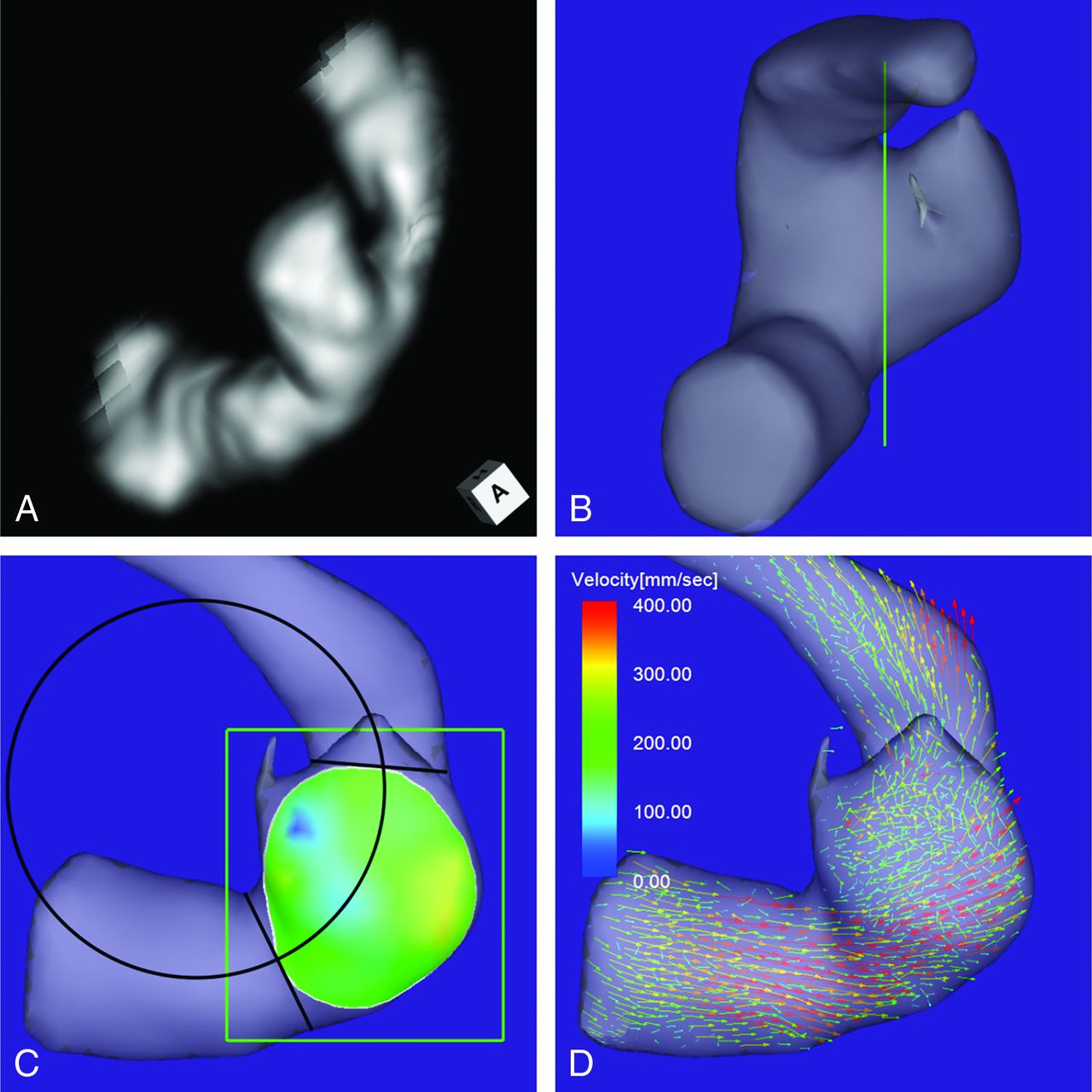
Case 2. An 80-year-old man had an unruptured aneurysm at the lateral C3 segment of the right ICA. A, A 3D TOF MRA image. B, Image shows the section plane corresponding to the aneurysm orifice. C, En face image of the section plane. A 4D flow MR image demonstrates the inflow zone (bright yellow) located on the lateral side of the neck and a circle in 2D fitting the central axis of the arterial part developing the aneurysm. The radius is 3.8 mm. D, A 4D flow MR image demonstrates a velocity vector map at peak systole, revealing that high-velocity vector components continue along the external side of the parent artery curvature.
Case 3.
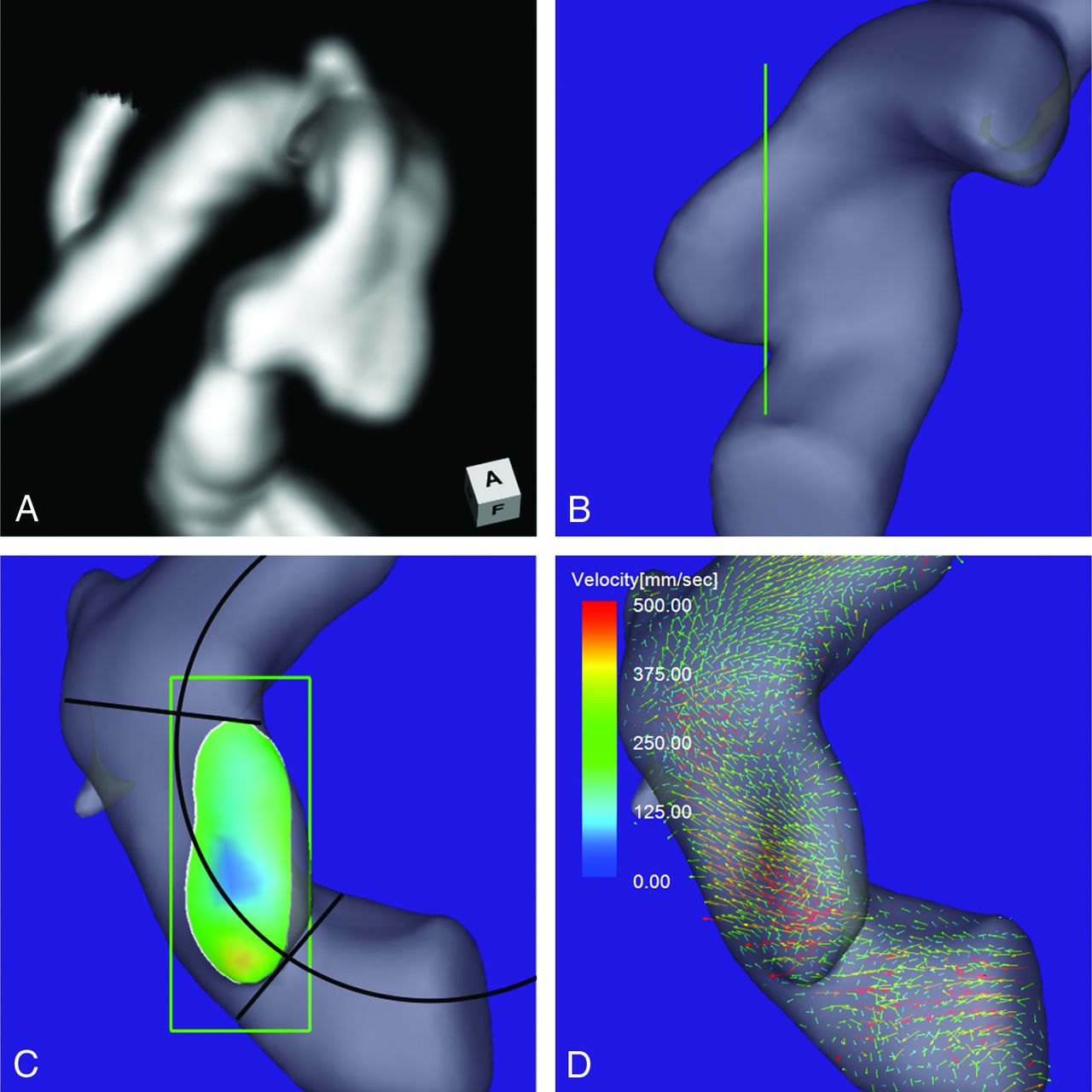
A 73-year-old man presented with an unruptured aneurysm at the medial C2 segment of the right ICA. Its maximum diameter and maximum neck diameter were 4.6 and 5.0 mm, respectively (Fig 4A). The inflow zone was located in a part of the proximal neck that extended beyond the central axis of the parent artery (Fig 4C). The radius was 4.9 mm. A velocity vector map at peak systole revealed that high-velocity vector components continued along the external side of the parent artery curvature (Fig 4D).

Case 3. A 73-year-old man had an unruptured aneurysm at the medial C2 segment of the right ICA. A, A 3D TOF MRA image. B, Image shows the section plane corresponding to the aneurysm orifice. C, En face image of the section plane. A 4D flow MR image demonstrates the inflow zone (orange) located in a part of the proximal neck extending beyond the central axis of the parent artery and a circle in 2D fitting the central axis of the arterial part developing the aneurysm. The radius is 4.9 mm. D, A 4D flow MR image demonstrates a velocity vector map at peak systole revealing that high-velocity vector components continue along the external side of the parent artery.
Discussion
The exact inflow zone location of sidewall aneurysms remains controversial.12,15,16,30⇓–32 Previous studies have recognized that the inflow zone of sidewall aneurysms is consistently on the distal neck.30,31 In contrast, Szikora et al16 reported that the inflow zone could be on the proximal neck in most sidewall aneurysms with a wide neck. Sforza et al32 classified the locations of the inflow zones into the distal neck, side of the neck, and proximal neck by computational fluid dynamics analysis by using patient-specific models. However, they did not clarify the incidence of aneurysms in each location of the inflow zone and the factors for determining the location.32 Using 4D flow MR imaging, we recently reported that the inflow zone was not located on the distal neck in 25% of sidewall aneurysms.15 In this study, we defined the locations of the inflow zones more precisely by investigating the correlation between inflow zone location and parent artery central axis on the en face image of the section plane of the aneurysm orifice by using 4D flow MR imaging. Consequently, the inflow zone was located on the distal neck in 31.3%, the lateral side of the neck in 59.4%, and the proximal neck in 9.4% of unruptured sidewall ICA aneurysms.
Computational fluid dynamics analysis by using idealized models demonstrated that the parent artery curvature more closely influenced the inflow zone location than did aneurysm shape or size.3,4,19,33⇓–35 Imai et al19 and Sato et al35 revealed that the inflow zone was on the distal neck when idealized aneurysms were located inside or outside the parent artery curvature and that the inflow zone was on the outer side of the curvature when the aneurysms were located lateral to the same curvature. Their observations indicated that the parent artery curvature evaluated in 2D on an en face image of the section plane corresponding to the aneurysm orifice may influence the inflow zone location.
In this study, the radius in group 1 (the inflow zone located on the distal neck) was significantly larger than that in group 2 (the lateral side of the neck) or in groups 2 and 3 (the proximal neck). These results indicate that the parent artery curvature on an en face image of the section plane corresponding to the aneurysm orifice influences the inflow zone locations of the sidewall aneurysms. As shown in Fig 3D, in aneurysms with a small radius, the main flow in the vessel cavity is shifted to the lateral side of the artery by the centrifugal effect, resulting in the lateral side inflow zone location in group 2 aneurysms. All 7 aneurysms with a radius of >8.0 mm of the parent artery curvature in this study were in group 1. Aneurysms with a radius of >8.0 mm on 3D TOF MRA can be determined to be on the distal neck without the need for additional 4D flow MR imaging. These findings can help future investigators or clinicians infer the inflow zone location by using vascular curvature without having to perform flow imaging as in this study.
Szikora et al16 reported the possibility that neck size influences the inflow zone location and that in most sidewall aneurysms with a wide neck, the inflow zone could be in the proximal neck. In this study, we investigated the correlation between both the maximum and the width orifice ratios and the inflow zone location. However, there were no significant correlations. In addition, Sato et al35 demonstrated that the inflow zone location was not dependent on the aneurysm shape by computational fluid dynamics analysis by using idealized models. Likewise, the morphologic parameters in this study did not influence the inflow zone location. In 2 of 3 aneurysms with an inflow zone on the proximal neck, the inflow zone was located in a part of the neck extending beyond the central axis of the parent artery. This specific neck shape and the centrifugal effect of the blood flow in the vessel may cause the inflow zone to be on the proximal neck.
This study has some limitations. 4D flow MR imaging requires an imaging time of 20–30 minutes for each patient. This relatively long time can result in motion artifacts. In addition, 4D flow MR imaging may have the limitation of spatial resolution.15,22 These disadvantages can cause unstable and irregular streamline patterns irrelevant to the vascular shape on 4D flow MR images. High-resolution MR imaging at >3T may decrease these artifacts.22,36 Here we investigated the correlation between inflow zone location and the curvature of the arterial part of developing aneurysms evaluated in 2D on an en face image of the section plane corresponding to the aneurysm orifice. However, the parent artery curvature proximal to the aneurysms can also influence the location of the main flow stream in the vessel cavity and the inflow zone.22,35 Further studies are needed to clarify the influence of the 3D parent artery curvature on the inflow zone location.
Conclusions
The inflow zone locations of sidewall aneurysms can be influenced by parent artery curvature evaluated in 2D on an en face image of the section plane corresponding to the aneurysm orifice. The inflow zone of all aneurysms with a radius of >8.0 mm was located on the distal neck, while that of all aneurysms with a radius of <6.0 mm was located on the lateral side of the neck or the proximal neck.
REFERENCES
- Received May 21, 2014.
- Accepted after revision August 13, 2014.
- © 2015 by American Journal of Neuroradiology


