
We thank Treuer et al for their interest in our article “Determining the Orientation of Directional Deep Brain Stimulation Electrodes Using 3D Rotational Fluoroscopy.”1 The coordinates (x, y, z) and 2 angles (pitch and yaw angles) are required to describe the position of a nondirectional deep brain stimulation (DBS) lead, and determining these is routine clinically. In directional leads, a third angle (roll) needs to be considered. We investigated the “iron sights method” to additionally determine this angle because there was no known imaging technique allowing us to do so precisely. We could demonstrate that this method allows determining a lead orientation angle with high interrater reliability.1 We are aware that this angle is determined in a plane defined by 3D rotational fluoroscopy. As used in CT scans, the rotational fluoroscopy should be aligned to the tuberculum sellae–occipital protuberance line, and head tilt must be excluded by aligning both external acoustic meatus. This line closely correlates to the anterior/posterior commissure line,2 which defines the relevant plane in clinical DBS practice. In publications, typically the orientation of directional leads is described and depicted in this plane.3
3D rotational fluoroscopy allows reconstructing a volumetric dataset that can be fused with the preoperative, stereotactic CT or MR imaging scan as shown in Fig 1. Thus, after fusion with these images, the stereotactic coordinates together with the pitch and yaw angles can be determined in a stereotactic planning system, allowing the roll angle to be calculated for any desired plane. In addition, the surrounding anatomic structures can be visualized (eg, in the preoperative MR imaging).
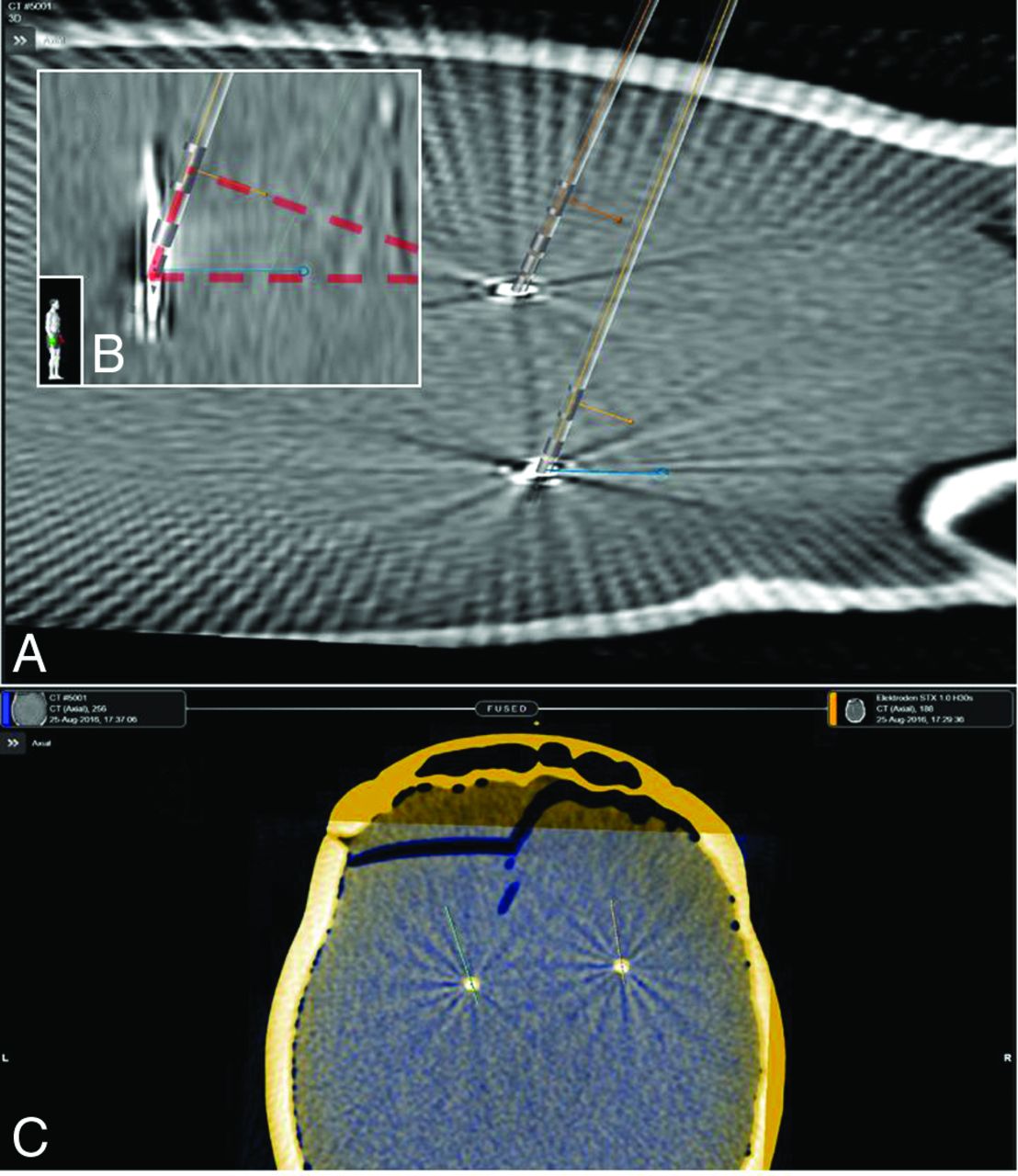
A, Visualization of 3D directional electrode models in a 3D reconstruction of rotational fluoroscopy imaging. The blue line (in-plane) indicates the detected orientation in the axial plane based on the iron sights method. The orange line originating out of the marker indicates the lead orientation. B, The same scene from a lateral view. The in-plane orientation and marker orientation form a rectangular triangle (red transparent) with the right angle at the marker. C, Fusion of rotational fluoroscopy 3D reconstruction and the CT scan in Brainlab Elements (Brainlab, Munich, Germany).
To address the authors' comment (additionally using ground truth and to further investigate the influence of different implantation angles on the iron sights method), we embedded a directional lead in an acrylic glass cylinder. This model was fixed in a stereotactic frame (Leksell G frame; Elekta Instruments, Stockholm, Sweden) and oriented visually with the marker exactly facing anteriorly. This orientation was confirmed by a strictly lateral x-ray in respect to the stereotactic frame. To investigate in which angles the overlap of the gaps between the electrode segments was still visible, we performed digital x-ray and 3D fluoroscopy in different settings of the stereotactic system. We systematically (in steps of 10°) changed the arc and ring angles, resulting in polar lead angles of 0°–90° (ring, rotation in the sagittal plane) and 0°–60° (arc, rotation in the coronal plane) (Fig 2).

A, A directional lead embedded in an acrylic glass cylinder (ground truth). This model was fixed in a stereotactic Leksell G frame (Elekta Instruments) and oriented visually and with stereotactic fluoroscopy with the marker exactly facing anteriorly. B, Fluoroscopy was aligned with the stereotactic frame. C, The arc angle (lead rotation in the coronal plane) was changed to polar angles of 0°–60° in steps of 10°. D, The ring angle (lead rotation in the sagittal plane) was changed, resulting in polar angles of 0°–90° in steps of 10°. Digital x-ray and 3D fluoroscopy were performed for each setting to investigate in which angles the overlap of the gaps between the electrode segments (iron sights) is visible.
Fluoroscopically with unchanged rotation of the lead, the overlap of the gaps between the directional contacts remained visible up to a polar angle of 50° when tilting the lead toward the observer (arc angle). It was overlaid by the other contacts at 60°. The overlap of the gaps remained visible from 0° to 90° on rotation of the electrode in a sagittal plane (ie, the ring angle of the stereotactic system). Within these ranges, the iron sights visualization was possible for combinations of lead rotations in both planes.
As long as the overlap of the gaps was visible, 3D rotational angiography allowed determining the lead rotation using the iron sights method as in our previous phantom study.1 High polar angles (in our method, >50° in the coronal plane) require an oblique 3D fluoroscopy plane.
Sitz et al4 have shown in their phantom study, evaluating the CT artifacts of the directional marker to determine the lead orientation, that “for polar angles >40°, the results became erratic and the uncertainty increased to ± 8.9° (range −23° to 34°).” They explained this with the marker anatomy, “Distal parts of the marker with the ring-shaped structures also appear within the CT-sections, giving rise to an additional nonisotropic artifact.”4
We analyzed the polar angles of all DBS implantations performed in our center in 2016. Regarding 107 DBS electrodes in 54 patients, the mean sagittal polar angle was 15.5° ± 29.8° and the mean coronal polar angle was 23.1° ± 9.9°. In 9/214 measured polar angles (4.2%), the value was >50°. In these cases, a modification of our standard 3D fluoroscopy scanning protocol (ie, alignment to the tuberculum sellae–occipital protuberance line) with an oblique scan is necessary. However, this can be precisely predicted from the stereotactic planning of the DBS procedure.
- © 2017 by American Journal of Neuroradiology


Jump to section
Related Articles
Cited By...
- No citing articles found.