
Abstract
BACKGROUND AND PURPOSE: When exposure and visual access in aneurysmal microsurgery are limited, exact intraoperative information must be obtained regarding the whole shape of the aneurysm, property of the aneurysmal wall, vessels hidden behind the aneurysmal sac, and surrounding bony structures of the skull base. We developed a transluminal imaging technique that uses 3D MR and CT angiograms and applied it for intraoperative transparent evaluation of the angioarchitecture of cerebral aneurysms.
METHODS: Transluminal images were reconstructed from a perspective volume-rendering algorithm by selecting information on the luminal margin from the whole volume data sets of MR and CT angiograms. The images show the vessel and aneurysmal walls as a series of rings and provide direct visualization of the underlying objects through the spaces between the rings. By connecting a graphic workstation to the operative microscope, data were reconstructed intraoperatively and adjusted to coincide with the operative views by manipulating the projection and visual angle. The aneurysmal angioarchitecture could then be evaluated transparently on the reconstructed transluminal images through the operative approach.
RESULTS: Transluminal images provided direct transparent visualization of the aneurysmal architecture, including orifices at the neck, dome, and bleb and the parent arteries though the vessel and aneurysmal walls. The angioarchitecture of the neck complex was evaluated intraoperatively with transluminal 3D MR and CT angiograms through the operative approach before actual aneurysmal neck clipping.
CONCLUSIONS: Intraoperative exact evaluation of aneurysmal angioarchitecture with transluminal images would be a feasible and useful adjunct for aneurysmal microsurgery. Merging of data across modalities including 3D MR and CT angiography may improve preoperative or intraoperative evaluation of the angioarchitecture of cerebral aneurysms.
Current advances in MR and CT angiographic techniques provide invaluable volume data on the angioarchitecture of cerebral aneurysms as a noninvasive method, which has demonstrated positive effects, not only in clinical diagnosis but also in therapeutic management of cerebral aneurysms, including surgical and interventional procedures (1–11). Three-dimensional reconstruction of the luminal data shown by MR and CT angiograms would represent the anatomic spatial relationship and morphologic features of the parent arteries and an aneurysm.
By using reconstruction software for computer medical visualization at a workstation, specific and limited data can be selected from a whole volume data set, based on the opacity chart of MR signal intensities (in arbitrary units) or CT attenuation (in HU). We have developed a transluminal imaging technique for visualization of an object transparently through the vessel lumen by using 3D MR and CT angiograms, in which information of the outer margin of the vessel lumen is selected from the volume data set and represents the contour of the vessels and aneurysms as a series of rings (12–15). Transluminal imaging allows a transluminal view from outside or inside the vessel lumen through the spaces between the rings and provides direct visualization of the underlying objects through the lumina.
In the present study, we analyzed our initial experiences with intraoperative evaluation of aneurysmal architecture with use of transluminal 3D MR and CT angiograms (12, 13). By connecting a graphic workstation to the operative microscope, data were reconstructed intraoperatively and adjusted to coincide with the operative views by manipulating the projection and visual angle within a short time; reconstructed images of either conventional or transluminal 3D MR and CT angiograms were depicted on the monitor display and/or in the inserted frame within the in-field monitor of an operative microscope. The angioarchitecture of the aneurysm, including the neck, dome, and bleb and the parent arteries, could then be evaluated transparently on the transluminal images through the operative approach before actual aneurysmal neck clipping. The feasibility and limitation of the intraoperative evaluation of aneurysmal architecture are discussed, with some comments on the characteristics of information obtained by conventional and transluminal 3D MR and CT angiography.
Methods
We studied two cases of an unruptured cerebral aneurysm detected incidentally on MR angiograms: an internal carotid-posterior communicating artery aneurysm and a distal anterior cerebral artery (A2–3) aneurysm. The aneurysms were surgically treated with use of the intraoperative reconstructed images, depicting the aneurysms with conventional and transluminal 3D MR and CT angiograms through an operative projection.
MR Angiographic Data Acquisition
We used a 1.0-T MR imager (Signa HiSpeed; GE Medical Systems, Milwaukee, WI) for MR angiography. Images were obtained with a 3D time-of-flight, spoiled gradient-recalled acquisition in the steady state sequence. Imaging protocol was as follows: 35/ 3.9–4.1/2 (TR/TE/excitations), flip angle of 20°, 192 × 128 matrix, 1.2-mm thickness, 0.6-mm section interval, 16-cm field of view, without magnetization transfer contrast, total imaging time 8 minutes 49 seconds (two slabs), 60 sections in total (two slabs), zero-fill interpolation processing two times, overlap of eight sections. A total of 104 source axial images were obtained, and those volume data were transferred to a workstation (Zio M900; AMIN, Tokyo, Japan), where the medical visualization software was installed on a commercially available graphic personal computer (Precision 530; Dell Computer, Austin, TX), running on the Windows 2000 Professional (Microsoft, Redmond, WA).
Reconstruction of Transluminal 3D MR Angiographic Data
The data sets were reconstructed every 0.3 mm, then processed into a 3D volume-rendering data set in 9 seconds. The conventional parallel and/or perspective 3D MR angiograms were created from the data set in 11 seconds by parallel and/or perspective volume-rendering algorithms (13, 15), by using a function of an increasing curve starting with a threshold of 145 (0% opacity level) up to 155 (100% opacity level). For transluminal imaging, the signal intensity representing the luminal margin on source images was matched to an opacity chart of MR signal intensities (in arbitrary units) by using a spiked peak curve function with a threshold range of 145–155 (peak value at 150 with 100% opacity level, window width 10). The resultant transluminal 3D MR angiogram represented the contours of the vessel and aneurysmal walls as a series of rings, color-coded in purple. The transluminal angiogram provided a transluminal view from outside or inside the vessel lumen through the spaces between the rings. The viewing projection for the perspective image was indicated by arrows on the source axial image, the coronal and sagittal reconstructions, and the 3D volume-rendered image. Reconstruction parameters of the function curve, including opacity level and range of values, was saved as a template on the workstation, so that the reconstructed images could be reproduced and used for the following intraoperative reconstruction.
CT Angiographic Data Acquisition
CT angiography was performed by using a helical CT scanner (Legato Duo; GE-Yokogawa Medical Systems, Tokyo, Japan). The protocol used was as follows: helical acquisition by using 100 mL of Optiray (iodine concentration 320 mg/mL; Yamanouchi Pharmaceutical, Tokyo, Japan) injected at a rate of 2 mL/s into the antecubital vein with a power injector (Dynamic CT injector MCT320P; Medrad, Pittsburgh, PA) and acquisition starting 21 seconds after the beginning of the injection, table speed of 1 mm/s, 1-mm collimation, 135-kV peak, 130 mA, 23-cm field of view, and a 512 × 512 matrix. A total of 38 sections were obtained with a section thickness of 1 mm. The data of the source axial images were reconstructed every 0.5 mm with a 10-cm field of view on the console, and then transferred to the same workstation used for MR angiograms.
Reconstruction of Transluminal 3D CT Angiographic Data
The data were reconstructed again every 0.25 mm on the workstation, then processed into a 3D volume-rendering data set. The conventional 3D CT angiograms were created from the data set by parallel and/or perspective volume-rendering algorithms (12), by using a function of an increasing curve starting with a threshold of 85 HU (0% opacity level) and proceeding to 95 HU (100% opacity level). Transparency of the vessel and aneurysmal walls was determined by selecting the data set from the opacity chart of CT attenuation (in HU) by using a function of a spiked peak curve with a threshold range of 85–95 HU (peak value at 90 HU with 100% opacity level, window width 10 HU). The transluminal 3D CT angiogram represented the contours of the vessel and aneurysmal walls as a series of rings, color-coded in gray. The bony structures of the cranial base and calcification of the artery were emphasized by using a function of another square peak curve from the same opacity chart of CT attenuation with a threshold range of 250–400 HU, color-coded in red.
Intraoperative Reconstruction of 3D MR and CT Angiograms for Evaluation of Aneurysmal Architecture
For the intraoperative evaluation of aneurysmal architecture at aneurysmal microsurgery, we developed a system to provide a reconstructed image both on the monitor display connected to the operative microscope and in the inserted frame within the microscopic finder. The workstation was moved to the operating room and directly connected to the operative microscope system (OME-8000; Olympus, Tokyo, Japan), with a function for inserting an optical image with in-field monitor together in the operative microscopic finder. Schematic illustration of the setting for an intraoperative image reconstruction system is shown in Fig 1.
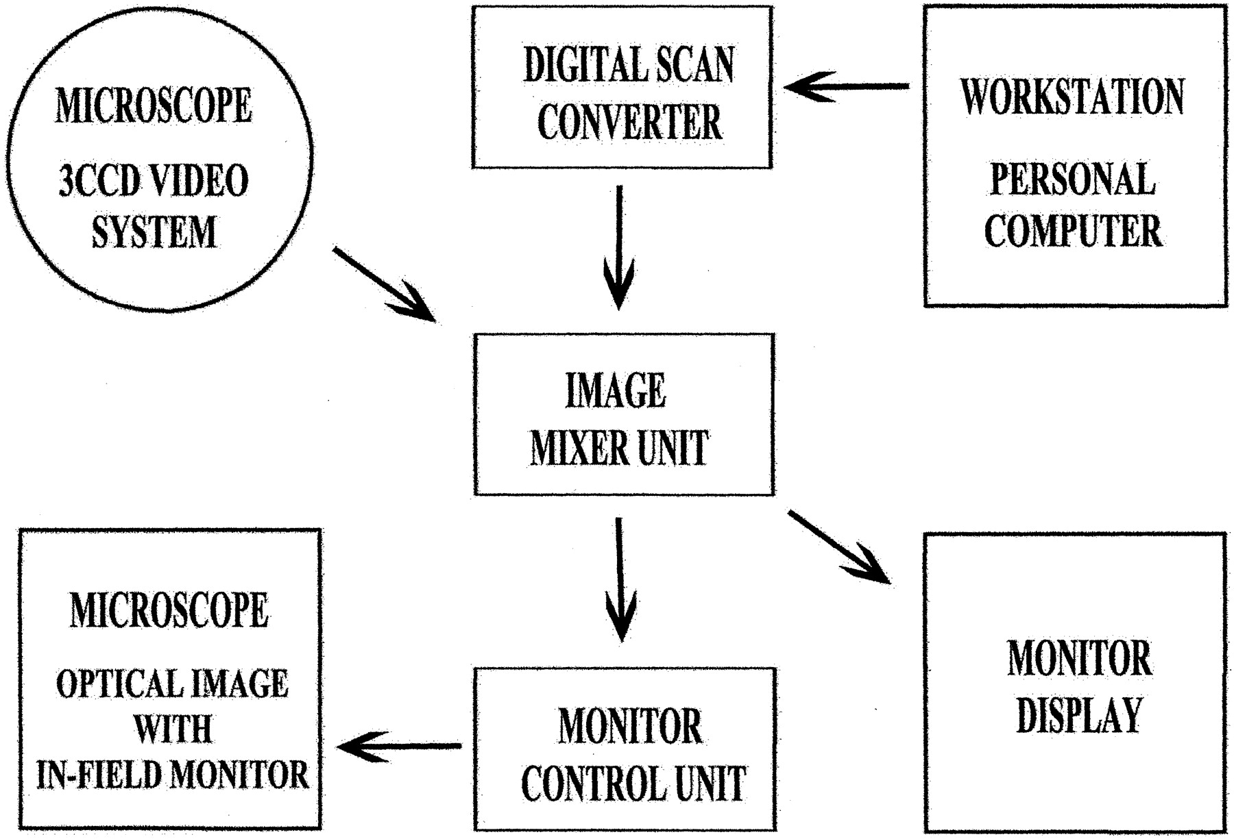
Schematic illustration of the setting for an intraoperative image reconstruction system.
By using reconstruction parameters of the function curves saved on the workstation, the conventional and transluminal volume-rendered images for both 3D MR and CT angiograms were reproduced in the operating room. Reconstructed images were adjusted intraoperatively to provide a projection and visual angle corresponding to the operative view. Average time required for reconstruction was 11 seconds per image. The spatial relationship within the angioarchitecture of the aneurysm including the neck, dome, and bleb of the aneurysm and the parent and branching arteries was evaluated on the reconstructed images. Transparent observation of the aneurysmal neck complex was made possible with the transluminal 3D MR and CT angiograms, and the clipping approach was evaluated on those reconstructed images before actual neck clipping of the aneurysm.
Results
The transluminal 3D MR and CT angiograms represented the configuration of the luminal wall of parent arteries and an aneurysm as a series of rings, also showing the neck, dome, and bleb, in contrast to conventional images, which represented those objects bounded by walls of space-occupying structures. Those images were reconstructed preoperatively, then reproduced and depicted intraoperatively on the monitor display of the operative microscope or in the inserted frame within the microscopic finder, but their projections and visual angles needed to be adjusted according to the operative visual field.
Case 1
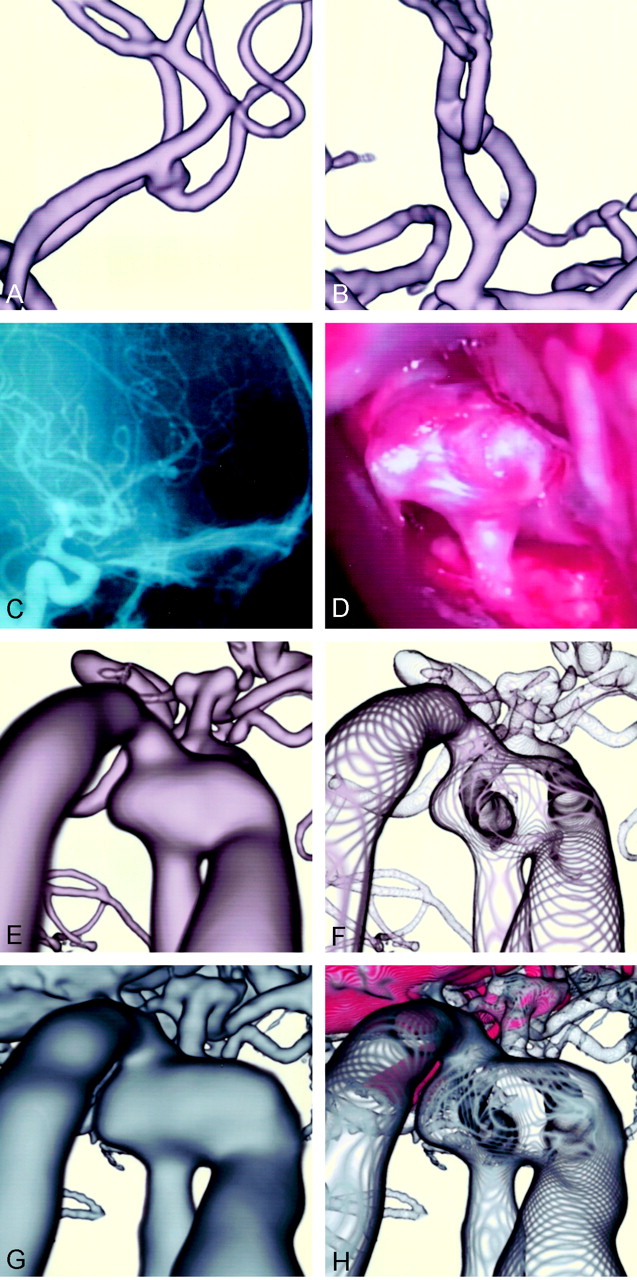
A 74-year-old man had an unruptured right internal carotid-posterior communicating artery aneurysm at presentation. The conventional parallel volume-rendered 3D MR angiogram (Fig 2A), 3D CT angiogram (Fig 2B), and cerebral arteriogram (Fig 2C) showed the aneurysm (10.2 × 7.3 mm) with a bleb (4.1 × 4.3 mm) at the superoposterior aspect of the dome. The operative view before neck clipping (Fig 2D) showed the anteroinferior aspect of the neck and dome of the aneurysm and the posterior communicating artery running behind the dome and along the carotid artery. An atherosclerotic lesion of the wall was observed on the internal carotid artery and base of the aneurysmal neck. The conventional perspective volume-rendered image of 3D MR angiogram (Fig 2E) showed an extensive view of the angioarchitecture of the aneurysm, including the dome, internal carotid artery, and branching posterior communicating artery, depicted similarly to that of the operative view. The precise feature at the proximal neck, however, showed a slight concavity, which differed from the operative findings. The transluminal 3D MR angiogram of the same projection (Fig 2F) depicted the orifice of the posterior communicating artery at the proximal neck, with its course running beneath the aneurysmal neck along the internal carotid artery. A bleb located on the backside of the distal neck, as shown in Fig 2A, was visualized through the dome. The conventional 3D CT angiogram (Fig 2G) depicted similar aneurysmal architecture, with the surrounding veins and bony structures. Tiny double convolutions were visible at the proximal neck, similar to the operative findings in Fig 2D and different from the 3D MR angiogram (Fig 2E). The transluminal 3D CT angiogram (Fig 2H) represented similar findings to those of the 3D MR angiogram; in addition, calcified nodules at the neck, color-coded in red, were identical to the tiny double convolutions.

Case 1: A 74-year-old man with an unruptured right internal carotid-posterior communicating artery aneurysm.
A, Conventional parallel volume-rendered 3D MR angiogram, viewed from above.
B, Conventional parallel volume-rendered 3D CT angiogram, viewed from above.
C, Arteriogram, similar projection to the operative view in D.
D, Operative photograph before aneurysmal neck clipping shows the neck and dome of the aneurysm. A yellowish-colored atherosclerotic lesion of the wall is observed on the internal carotid artery and base of the aneurysmal neck.
E, Conventional perspective volume-rendered 3D MR angiogram shows the aneurysmal dome, internal carotid artery, and branching posterior communicating artery.
F, Transluminal 3D MR angiogram of the same projection shows the orifice of the posterior communicating artery at the neck.
G, Conventional 3D CT angiogram shows similar aneurysmal architecture, with the surrounding veins and bony structures.
H, Transluminal 3D CT angiogram shows the transparent view of the aneurysmal architecture, with calcified nodules at the neck enhanced in red.
Case 2
A 55-year-old woman had an unruptured distal anterior cerebral artery (A2–3) aneurysm at presentation. The parallel volume-rendered 3D MR angiograms (Fig 3A and B) and cerebral arteriogram (Fig 3C) showed an aneurysm (5.5 × 3.9 mm) at the bifurcation of the left A2 and A3 that extended bilaterally, with the right side of the dome attached to the right A3. Operative findings through the right anterior interhemispheric approach (Fig 3D) showed the superoanterior aspect of the aneurysmal dome with the branching efferent distal artery. The dome extended bilaterally, and the right side of the dome was adhered firmly to the right A3. Because the aneurysmal neck was hidden by the foreground aneurysmal sac, the anteroinferior aspect of the neck was confirmed intraoperatively by moving the dome in the anteroposterior direction. The neck of the aneurysm was clipped side by side of each direction of the dome. The conventional perspective volume-rendered 3D MR angiogram (Fig 3E) showed the aneurysmal angioarchitecture including the aneurysmal dome, arteries originating from azygos A2, and efferent A3 arteries, similar to the operative view in Fig 3D. The transluminal MR angiogram of the same projection (Fig 3F) depicted the orifice of the afferent left A2 at the neck, with its course running below the aneurysmal dome originating from the azygos A2. The orifices from the dome to the efferent left A3 were transluminally visualized. Attachment of the right dome, which extended laterally to the right A3, was observed as an orifice-like opening on the right A3. The conventional 3D CT angiogram (Fig 3G) depicted the aneurysmal architecture with surrounding veins and frontal base bony structures. The transluminal 3D CT angiogram (Fig 3H) represented similar findings to those of the 3D MR angiogram with the frontal base bone color-coded in red; however, the bilaterally extended domes were shown larger than those on the 3D MR angiogram in Fig 3E and F.

Case 2: A 55-year-old woman with an unruptured distal anterior cerebral artery (A2–3) aneurysm.
A and B, Parallel volume-rendered 3D MR angiograms, right lateral (A) and anteroposterior (B) projections, show the aneurysm at the bifurcaton of the left A2 and A3, extending bilaterally, with the right side of the dome attached to the right A3.
C, Arteriogram, right lateral projection, shows the aneurysm.
D, Operative photograph through the right anterior interhemispheric approach, shows the superoposterior aspect of the aneurysmal dome with branching efferent artery. The right side of the dome is adhered firmly to the right A3, and the aneurysmal neck is hidden by the foreground dome.
E, Conventional perspective volume-rendered 3D MR angiogram shows the angioarchitecture of the aneurysm.
F, Transluminal 3D MR angiogram of the same projection shows the orifices of the afferent left A2 and efferent left A3 arteries transluminally through the vessel and aneurysmal walls.
G, Conventional 3D CT angiogram shows the aneurysmmal architecture with surrounding veins and frontal base bone.
H, Transluminal 3D CT anagiogram depicts similar findings as in G, with the frontal base bone color-coded in red.
Discussion
Characteristics of Volume Data Obtained by MR and CT Angiography
The volume data of MR angiography, performed with a 3D time-of-flight sequence, represent functional information related mainly to averaged peak inflow velocity within the vessel lumen during data acquisition (1–3, 7, 8, 13, 15). Intraluminal blood flow information on MR angiograms depicts an aneurysmal angioarchitecture that simply consists of arterial components. Because the MR angiogram provides relatively high signal intensity resolution with vessel lumina against surrounding structures, a paraclinoid internal carotid artery aneurysm is depicted without interruption of the cranial base bone and a middle cerebral artery aneurysm without overlying adjacent sylvian veins. However, depending on the aneurysmal geometry, such as the size of the neck and the flow ratio into the efferent branches, loss of signal intensity within an aneurysm can occur due to spin saturation effects with complex intraaneurysmal flow (15–17). MR angiograms may distort the shape of an aneurysm with inhomogeneous intraaneurysmal contents, as compared with the morphologic features shown by CT and digital subtraction cerebral angiograms. In addition, in a case of an aneurysm containing intraluminal thrombus or intramural calcifications, precise analysis of MR volume data may be affected by poor quality of the source images.
In contrast, CT angiography provides morphologic information by filling the vessel lumen with a contrast medium; it depicts the intraluminal configuration of the aneurysm and parent arteries along with surrounding structures including cranial base bone, veins, and pathologic calcification on the vessels (1, 4–6, 9–12). Intraluminal information indicated by CT attenuation consists of the volume of contrast medium delivered from blood flow during scanning. Representation on the CT angiogram is similar to that obtained by digital subtraction angiography; however, small vessels such as perforating arteries are often undetectable, and surrounding venous and bony structures overlapping the aneurysm are indistinguishable from the aneurysm because of the partial volume effect caused by relatively poor spatial and CT attenuation resolutions.
Transluminal Imaging with Perspective Volume-Rendering Algorithm
Currently, 3D reconstruction of volume data from MR and CT angiograms depicts the spatial relationship of aneurysmal architecture with fine morphologic configuration. By using conventional volume-rendering or surface-rendering algorithms, however, objects including vessels and an aneurysm are represented as space-occupying structures (1–11); the aneurysmal neck complex in the background is hidden by the foreground aneurysmal dome and parent arteries.
With application of transluminal imaging by means of a volume-rendering algorithm, information on the luminal margin is selected from the volume data sets, and the contours of vessel and aneurysmal walls are represented as a series of rings (12–15). Transluminal imaging allows a transparent view from outside or inside the vessel lumen through the spaces between the rings and provides direct visualization of underlying objects though the lumina. The orifices of the aneurysm and the parent arteries at the neck are shown through the vessel and aneurysmal walls. In addition, intramural calcification at the neck and parent arteries can be depicted on the transluminal 3D CT angiograms with a specific color for the realistic representation of the lesion.
The conventional parallel volume-rendering reconstruction technique depicts the object in parallel projection and provides a panoramic view; however, the background object along the projection is directly overlapped by the foreground structures. In contrast, reconstruction with a perspective volume-rendering algorithm provides an operative view from a viewpoint within a structural space (1, 3, 12–14). Accordingly, the background object can be depicted without overlapping of foreground obstacles, by changing view position. Perspective projection can provide continuity of the objects along the projection in perspective, so that the object is magnified in the near site with enlarged fine surface configuration, contrasting the reduction in the far site, depending on the visual angle. Consequently, perspective volume-rendering reconstruction techniques applied to transluminal 3D MR and CT angiograms can provide an extensive view of the angioarchitecture of the aneurysm through the restricted space, represented in perspective, similar to the operative view.
Intraoperative Evaluation of Aneurysmal Architecture with Conventional and Transluminal 3D MR and CT Angiograms
Preoperative exact evaluation of the angioarchitecture of a cerebral aneurysm is necessary for planning microneurosurgery, including information regarding the whole shape of the aneurysm, orifices of the aneurysm, and parent arteries at the neck, as well as the thickness and pathologic lesions of the aneurysmal wall and neck. In instances when exposure and visual access involved in aneurysmal microsurgery are limited, intraoperative geometric information concerning the spatial relationships of vessels and the surrounding perianeurysmal environment along the surgical approach is invaluable for surgical interventions.
By connecting a personal computer of the portable graphic workstation to the operative microscope system, an intraoperative evaluation of aneurysmal architecture becomes possible, providing reconstructed images of 3D MR or CT angiograms for the monitor display and/or the inserted frame within an in-field microscope finder. Several images for surgical approach are preoperatively reconstructed from the volume data set with the workstation and are then adjusted intraoperatively to coincide with the operative views by manipulating the projection and visual angle within a short time. Before actual clipping of the aneurysmal neck, the size, number, and approach direction of the clip can be decided based on the architecture of the aneurysmal neck complex depicted on the conventional and transluminal 3D MR and/or CT angiogram.
In contrast to the conventional images, transluminal images with either 3D MR or CT angiograms can provide a transparent visualization of the aneurysmal architecture through the operative approach. For cases in which the aneurysmal neck is hidden by the foreground aneurysmal sac, transluminal observation of the orifices at the neck may be especially useful in deciding the direction of clipping to avoid incomplete clipping or obliteration of branching arteries.
Limitaiton of Intraoperative Evaluation of Aneurysmal Architecture with 3D MR and CT Angiograms
Reconstruction of 3D images from the volume data sets, including conventional and transluminal volume-rendering imaging, is not time-consuming with advanced software for computer medical visualization applied to the workstation; intraoperative reconstruction of aneurysmal architecture to coincide with the operative views is simple and feasible for routine use in aneurysmal microsurgery. However, there are several limitations of intraoperative evaluation of aneurysmal architecture with reconstructed images of conventional or transluminal 3D MR and CT angiograms. The first limitation is that the diameter of the vessel lumen, reconstructed by a volume-rendering algorithm, varies depending on the MR signal intensities or CT attenuation selected for the vessel wall, so the threshold range of the function curve must be optimized based on the source images. Small arteries or perforators are not detected owing to the limitation of spatial resolution with the present MR and CT equipment. Second, reconstructed images may not be matched to the operative view because of the change in position of the brain parenchyma and vessels by intraoperative manipulation in surgical extension, but similarity in the architecture of an aneurysm is usually identical between reconstructed images and the operative view.
The third limitation is essentially due to the volume data obtained from intraluminal information with MR and CT angiograms. The CT angiogram shows intraluminal morphologic features of the vessels and aneurysm, and the MR angiogram provides flow-related intraluminal information; however, those images fail to depict the outer wall configuration of the aneurysm as encountered during aneurysmal microsurgery. A certain discrepancy may exist between the reconstructed images of 3D MR and CT angiograms and the intraoperative view, especially in cases of an aneurysm with intraaeurysmal thrombus, calcification, and thick atherosclerosis in the wall. The contours of the vessels can be depicted by using volume data obtained from MR and CT cisternograms, but they are limited within the cisternal space (14, 18, 19).
Conclusions
Transluminal imaging can provide direct transparent visualization of the aneurysmal architecture, including orifices at the neck, dome, and bleb and the parent arteries though the vessel and aneurysmal walls. Evaluation of the aneurysmal neck complex with transluminal 3D MR and CT angiograms would be a feasible and useful adjunct not only in clinical diagnosis but also in therapeutic management of cerebral aneurysms with surgical or interventional procedures. Merging of data across modalities including 3D MR angiography, CT angiography, and cerebral arteriography may allow us to overcome the shortcomings of each technique and improve preoperative or intraoperative evaluation of aneurysmal architecture. Further study is needed to delineate an aneurysm in contrast to the perianeurysmal environment on the preoperative and intraoperative reconstructed images, and to compare these images with intraoperative findings.
Footnotes
Pesented at the 60th annual meeting of the Japan Neurosurgical Society, Okayama, Japan, October 24, 2001.
References
- Received March 13, 2003.
- Accepted after revision June 17, 2003.
- Copyright © American Society of Neuroradiology
In this issue


Jump to section
Related Articles
Cited By...
- No citing articles found.